This post is part of the Production Line Alarms series.
Simple unit to silence the audible alarm on a production equipment, uses an AVR ATtiny2313 microcontroller.
Table of contents
Details
This module was built for a production equipment at my previous workplace, it made it possible for an operator to silence an alarm without resolving it. Fixing an error could take some time and having the alarm horn sound during that period was very annoying, so many operators removed the alarm relay. This was unfortunate because it was not always put back, so the next alarm situation could go unnoticed. This module would silence the alarm, but still reactive it once the situation had been resolved. Eliminating the need to remove the alarm relay. Powered by: 9-24V.
Operation
Alarm reset
When an alarm situation occurs the red LED flashes and the production alarm sounds, by pressing “reset alarm” the voltage to the sound alarm is cut. The red LED lights continuously when the alarm is reset. When the alarm situation is resolved the red LED turns off and the voltage to the sound alarm is restored. When a new fault occurs the procedure is repeated.
Service mode
During maintenance or other work where multiple alarms are expected; the module can be put in service mode. This will disable the alarm horn for 1.5 hours, after which the module will return to normal operation. Service mode is aborted if the “reset alarm” button is pressed.
Enter service mode
- No alarms must be present or silenced.
- Press and hold the “reset alarm” button for 20 seconds.
- Alarm LED will flash, let go of the “reset alarm” button within one second.
- The power LED will start flashing quickly to indicate that service mode is active.
I/O
Inputs
- PD.0 Reset button
- PD.1 Stack lights signal
Outputs
- PB.0 Red LED
- PB.1 Power LED
- PB.2 Stack lights relay N.O
D-Sub 9-pins
- 24V
- 0V
- Stack lights in + (to opto-isolator)
- Stack lights in - (to opto-isolator)
- Stack lights relay +
- Stack lights relay - N.O
Drawings
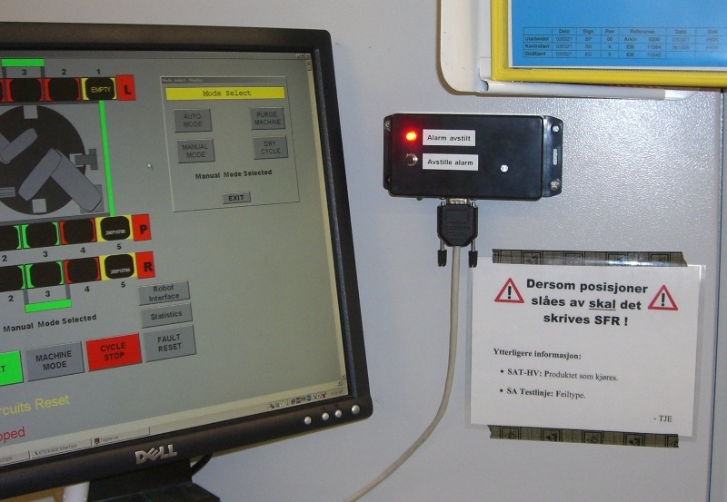
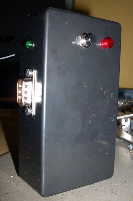
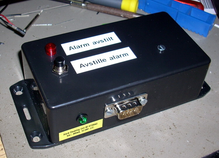
Panel front

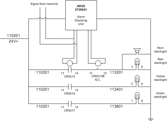
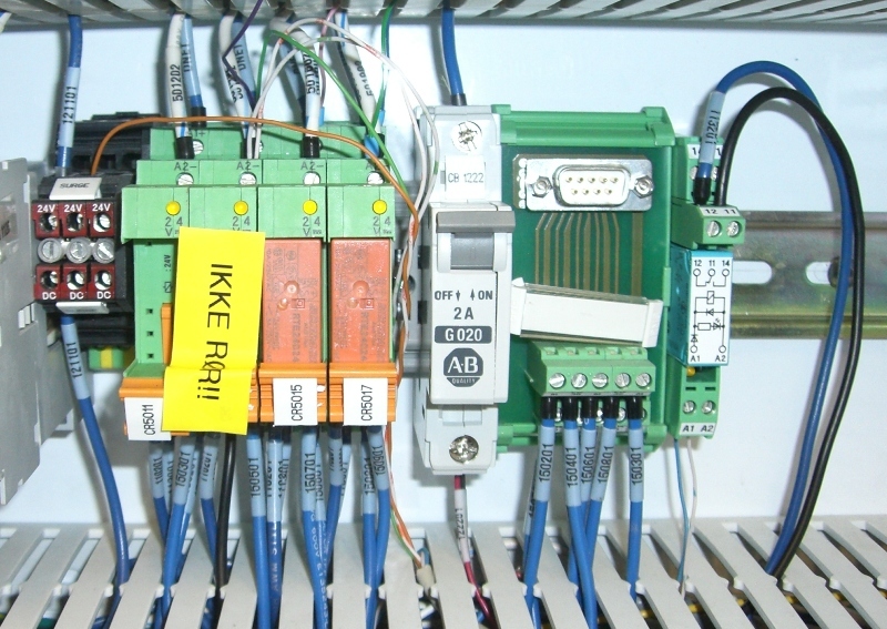
Inside equipment
Schematic drawing
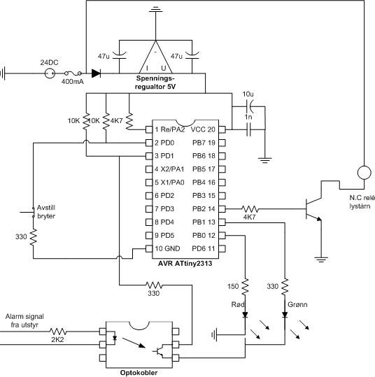
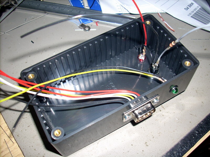
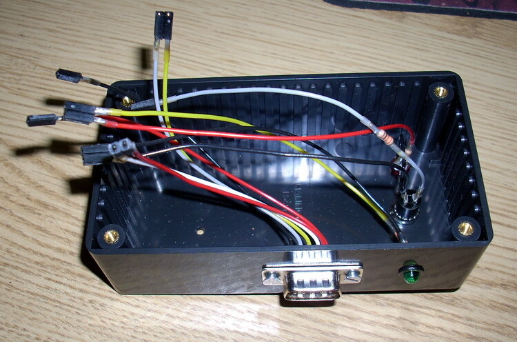
Internal connectors
- Signal from internal reset button (With resistor)
- 24V supply voltage
- Red : + (D-sub 1)
- Blue : - (D-sub 2)
- Status LEDs
- Red : + Red LED
- Green : + Green LED
- Signal from stack lights
- Red : + (D-sub 3)
- Blue : - (D-sub 4)
- GND to LEDs and switch
- 24V to stack lights relay (D-sub 5)
- GND to stack lights relay (D-sub 6)
Source code
- Bascom-AVR source is available in a git repository:
- https://github.com/thomasjsn/AVR-Alarm-disabling-2
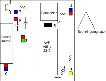
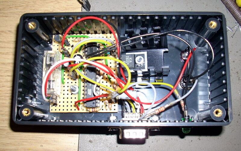
Photos
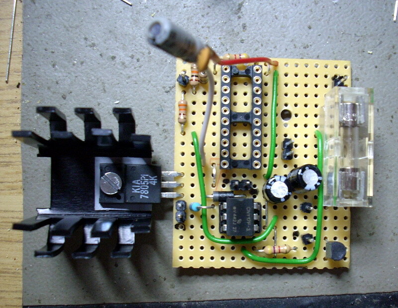
Parts list
- 1 × AVR ATtiny2313-20PU, DIL-20, 20 MHz, 18 I/Os
- 1 × Capacitor, aluminium electrolytic, 10 µF, 25V
- 2 × Capacitor, aluminium electrolytic, 47 µF, 25V
- 1 × Capacitor, ceramic, 1 nF, 100V
- 2 m Control cable, 8-cores, shield, 0.14mm2, 250 V, Ø 5.1mm
- 1 × D-sub plastic hood, 9-pin, black
- 1 × D-sub soldering cups, 9 pin female
- 1 × D-sub soldering cups, 9 pin male
- 1 × DIL socket, 20-pin, 7.62mm
- 1 × DIL socket, 6-pin, 7.62mm
- 1 × Diode, rectifier, 1 A, 400V, 1N4004
- 1 × Enclosure, plastic (1591 FL), 120x65x40mm, flange
- 1 × Fuse 5x20 mm, 400 mA, fast-acting
- 1 × Fuse holder, open, PCB, 5x20mm
- 1 × Fuse holder, open, PCB, Protective cover
- 1 × Heat conducting film for heatsink, Adhesive, TO220
- 1 × Heatsink, 15K/W @ 4W, 28mm 7g, TO220
- 1 × LED 5mm clear, Red, 2.1V, 20mA, 7.000mcd, 20°
- 1 × LED 5mm coloured clear, Green, 2.1V, 20mA, 30mcd, 10°
- 1 × LED holder 5mm, Black plastic
- 1 × LED lens 5mm, CLF 280, Red
- 1 × Optocoupler, single, CNY17F-3, DIL-6
- 32 cm2 PCB, stripboard, 100x160mm, 160cm2
- 1 × Resistor, carbon film, 0.25W, 150 Ω, 5%
- 3 × Resistor, carbon film, 0.25W, 330 Ω, 5%
- 2 × Resistor, carbon film, 0.25W, 4.7 kΩ, 5%
- 2 × Resistor, carbon film, 0.25W, 10 kΩ, 5%
- 1 × Resistor, metal film, 0.6W, 2.2 kΩ, 1%
- 1 × Spacer, round unthreaded, 3mm, Ø6mm, Delrin
- 11 × Straight pin header, female, Single row, 2.54mm
- 11 × Straight pin header, male, Single row, 2.54mm
- 1 × Switch, push-button, 1-pole, 1A, 50VAC, on-(off)
- 1 × Transistor, NPN, 100 mA, 45V, 0.5W, BC547B
- 1 × Voltage regulator +5V, 1 A, 7805PI
Last commit 2023-02-05, with message: Add series for production line alarms.
Production Line Alarms series
- AVR production line stop alarm
- AVR alarm disabling unit for production equipment with long stop warning
- AVR alarm disabling unit for production equipment