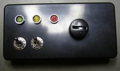
Auto and manual override control of a boat pump that I built for my dad’s sail-boat.
This is a very simple pump control unit, for boats with a water level sensor. Two modes can be selected:
- Auto; the pump start automatically on signal from the water level sensor.
- Manual; overriding the sensor, forcing the pump to run.
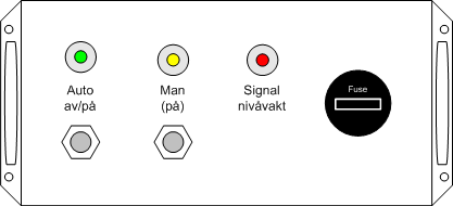
The unit can three LEDs:
- Green; auto mode has been selected.
- Yellow; the pump is running.
- Red; signal from water level sensor is active.
The relay, and fuse, is 10 A.
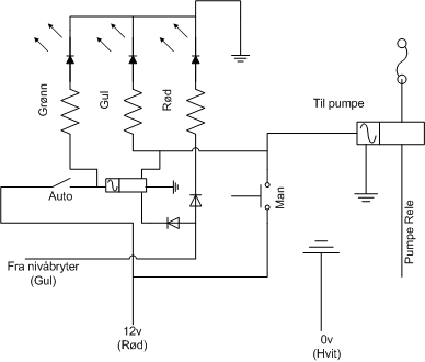
Schematic drawing
Parts list
- 2 × Diode, rectifier, 1 A, 400V, 1N4004
- 1 × Enclosure, plastic (1591 FL), 100x50x25mm, flange
- 1 × Fuse holder, panel, 5x20mm, PTF30
- 1 × LED 3mm, Green, 2.1V, 20mA, 3.5mcd, 38°
- 1 × LED 3mm, Red, 2.1V, 20mA, 1.0mcd, 38°
- 1 × LED 3mm, Yellow, 2.0V, 20mA, 2.5mcd, 38°
- 3 × LED holder 3mm, Chromed metal
- 1 × Relay, 1 CO, G2R-1, 12 VDC, 10A 230V
- 1 × Relay, 2 CO, HJR1-2C, 12 VDC, 1A 120V, PCB
- 3 × Resistor, metal film, 0.6W, 1 kΩ, 1%
- 1 × Switch, toggle, 1-pole, micro, on-(on)
- 1 × Switch, toggle, 1-pole, micro, on-on
Last commit 2021-03-04, with message: publish old posts