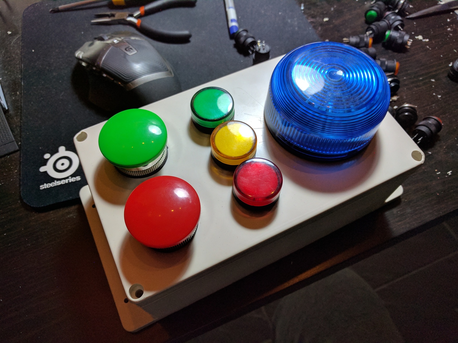
My twin boys are, like their dad, fascinated by switches and flashing lights. I needed an excuse to use the Raspberry Pi Zero in a project, so I built them a WiFi MQTT controlled alarm module. With a couple of switches, some panel indicators, a buzzer, and a blue LED strobe.
Table of contents
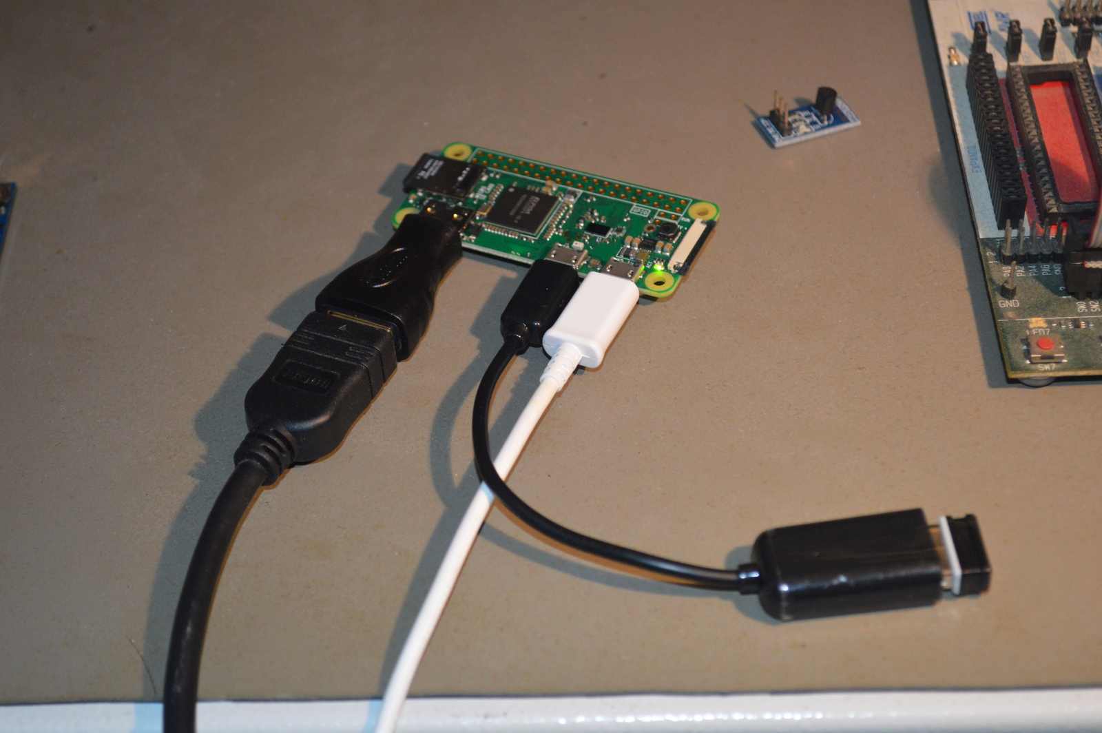
Raspberry Pi Zero
An advantage of using a Raspberry Pi, instead of e.g., Arduino, is that I can easily SSH into it and modify the code. And I can program in Python, which I rather enjoy.
First, I needed to get the Raspberry Pi up and running. I have written a post about that, where I go into details on how to get the Raspberry Pi ready, so I won’t cover that here.
The build
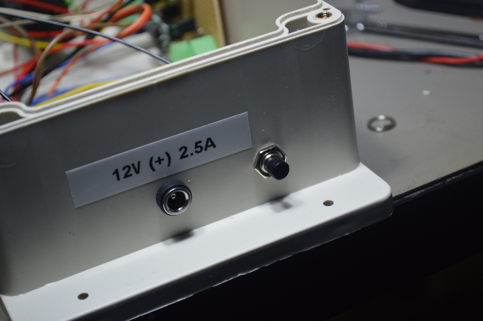
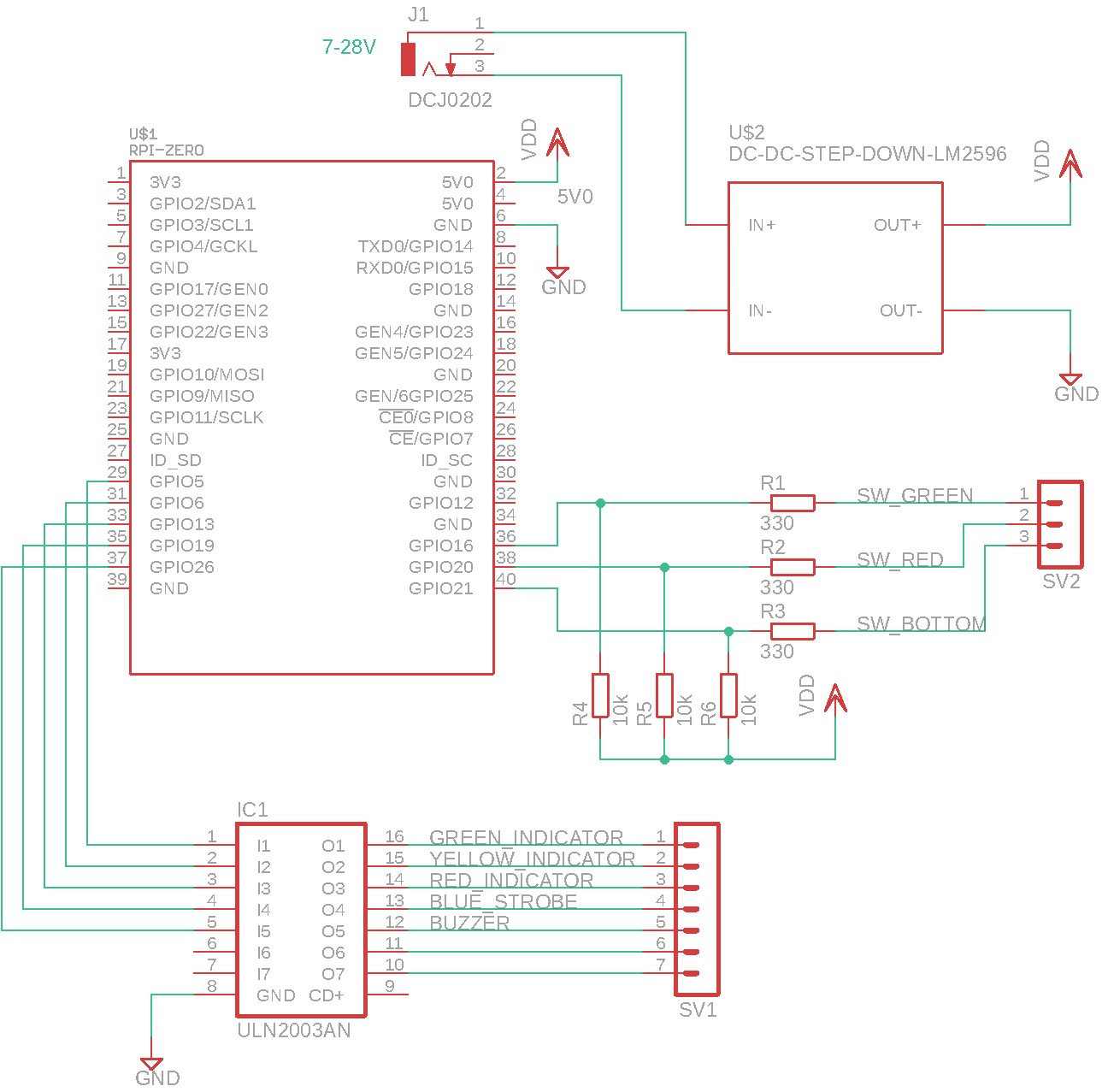
To power the Raspberry Pi Zero, I am using a 5V step-down converter, connected to the micro USB port on the Raspberry Pi. I’m using 12V as input, as that will power all the LEDs, the buzzer, and the strobe.

For the outputs, I’m using a Darlington driver, ULN2003A. It is pretty much perfect for this application; it is compact, has base resistors, and take 5V on the inputs. The Raspberry Pi doesn’t have 5V on its GPIO, it has 3.3V, but I found this works just as well with the ULN2003A.
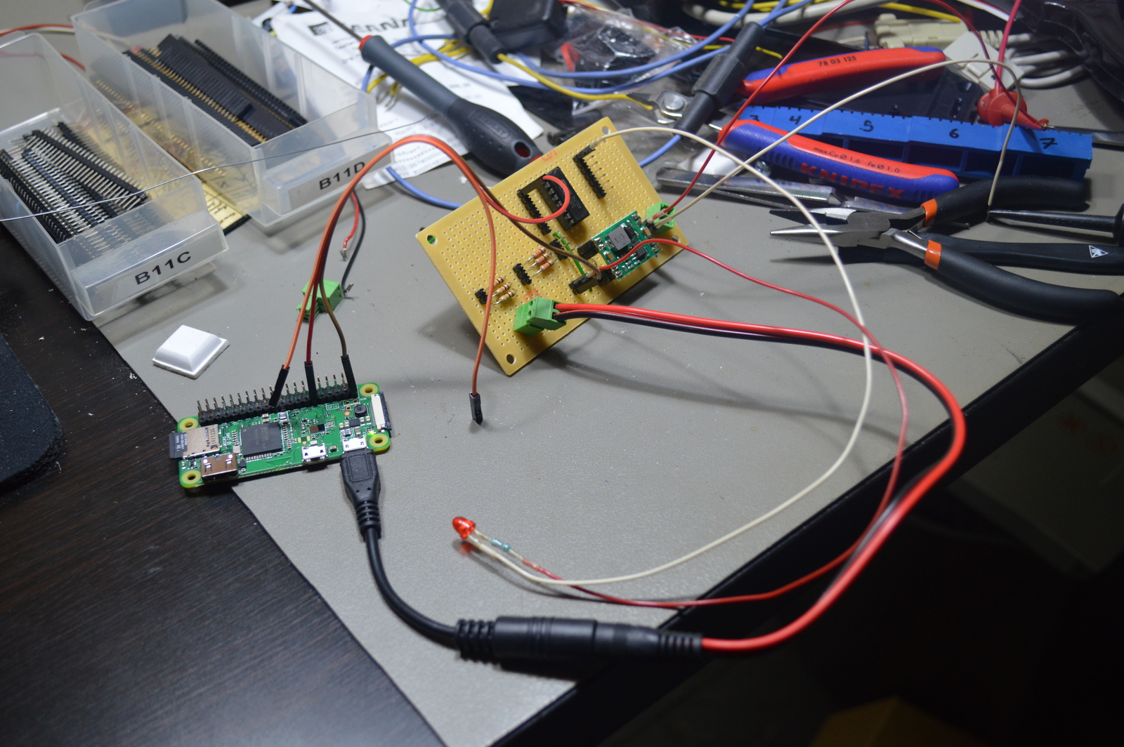
The inputs have 10K pull-up resistors, with 330 in series with the Raspberry Pi GPIO input. Probably best explained by the schematic drawing.
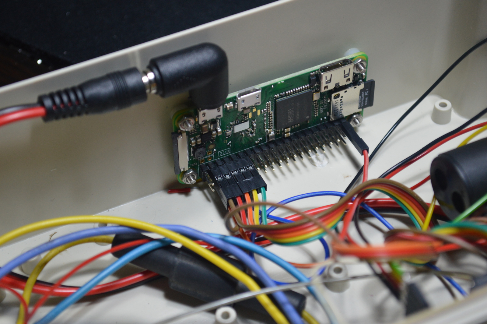
I soldered the step-down converter, Darlington driver, and input resistors to a prototype board and mounted it to the inside wall of the plastic enclosure. On the opposite side, I installed the Raspberry Pi Zero.
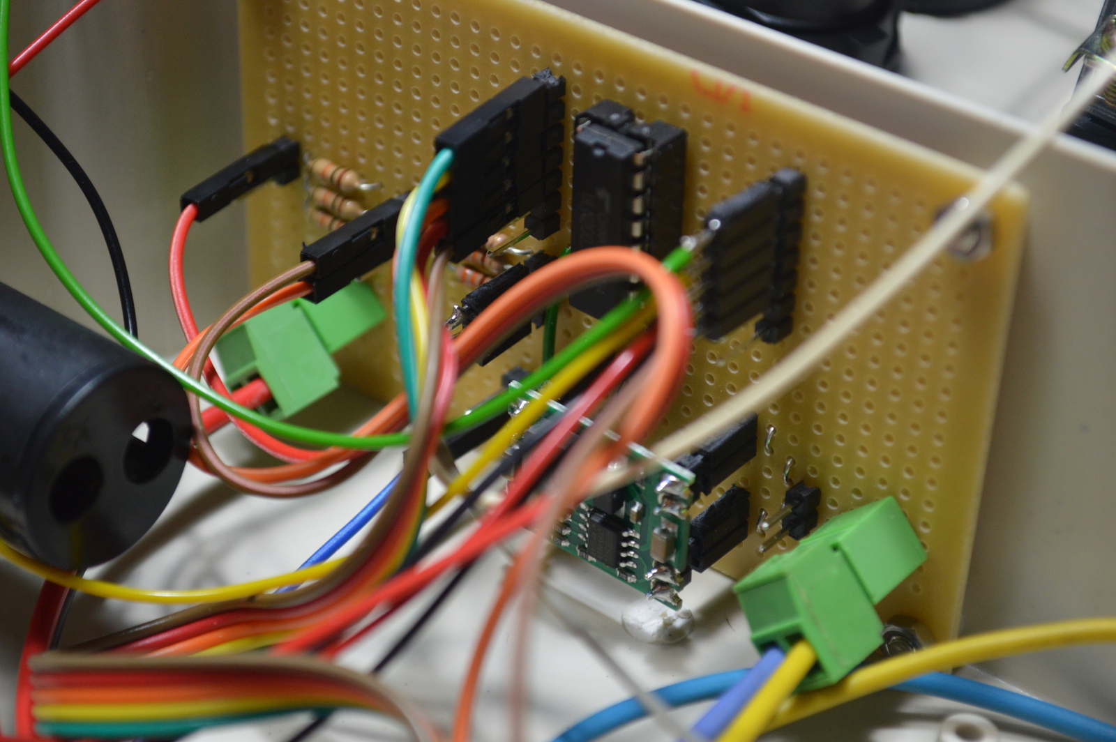
For connecting the prototype board and the Raspberry Pi GPIOs, I used single Dupont wires. That allowed me to link only to the pins I needed on the Raspberry Pi, and use colors that made sense.
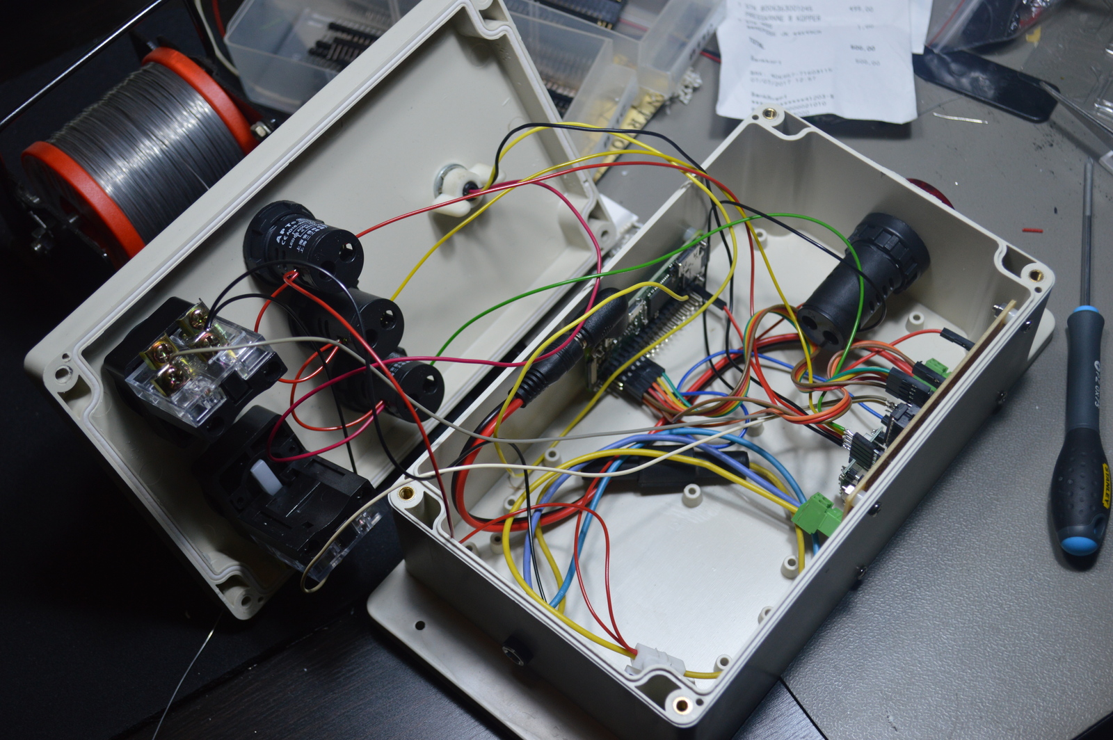
I then mounted the switches, LEDs, buzzer, and strobe and wired them to the prototype board.
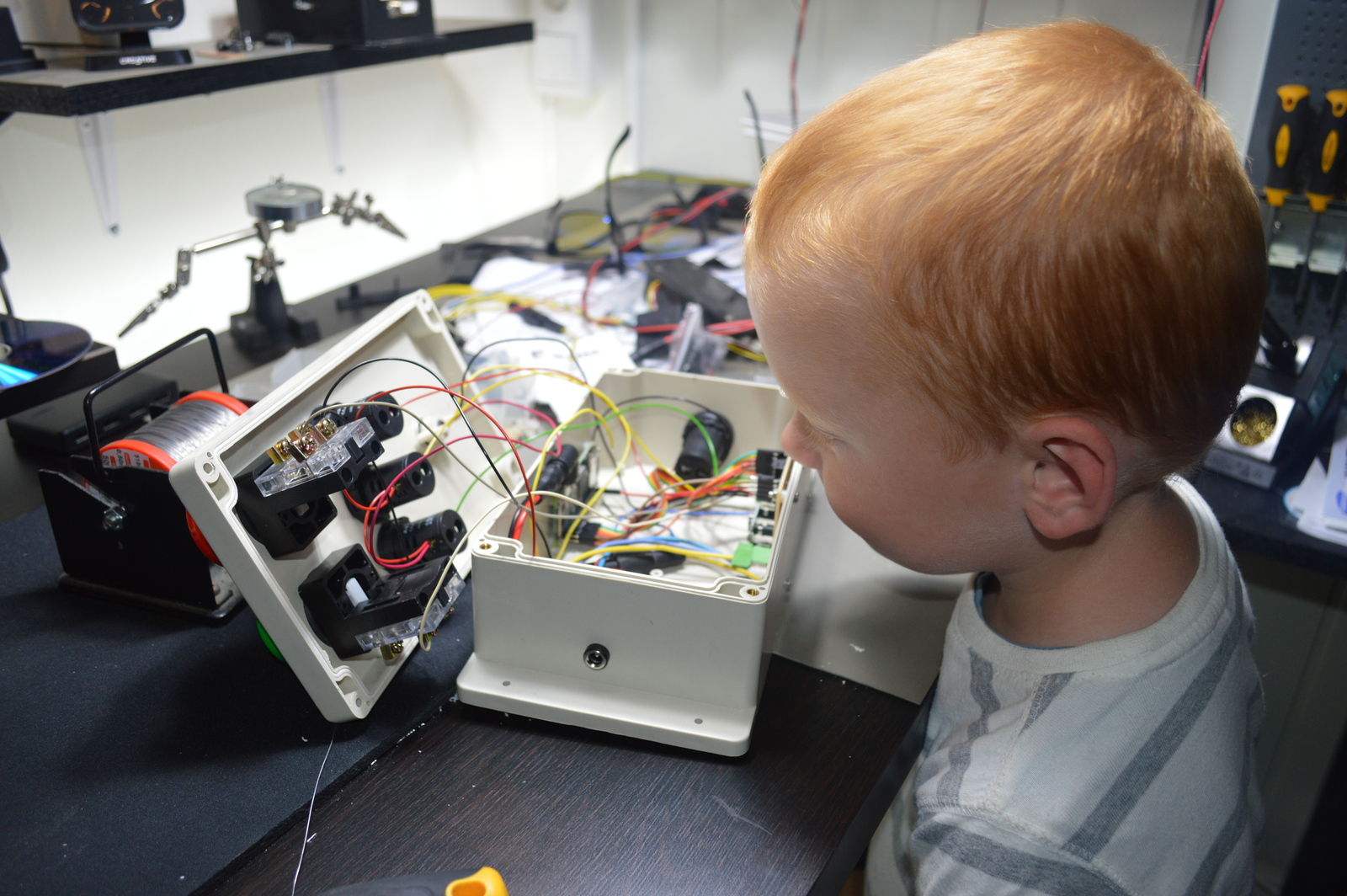
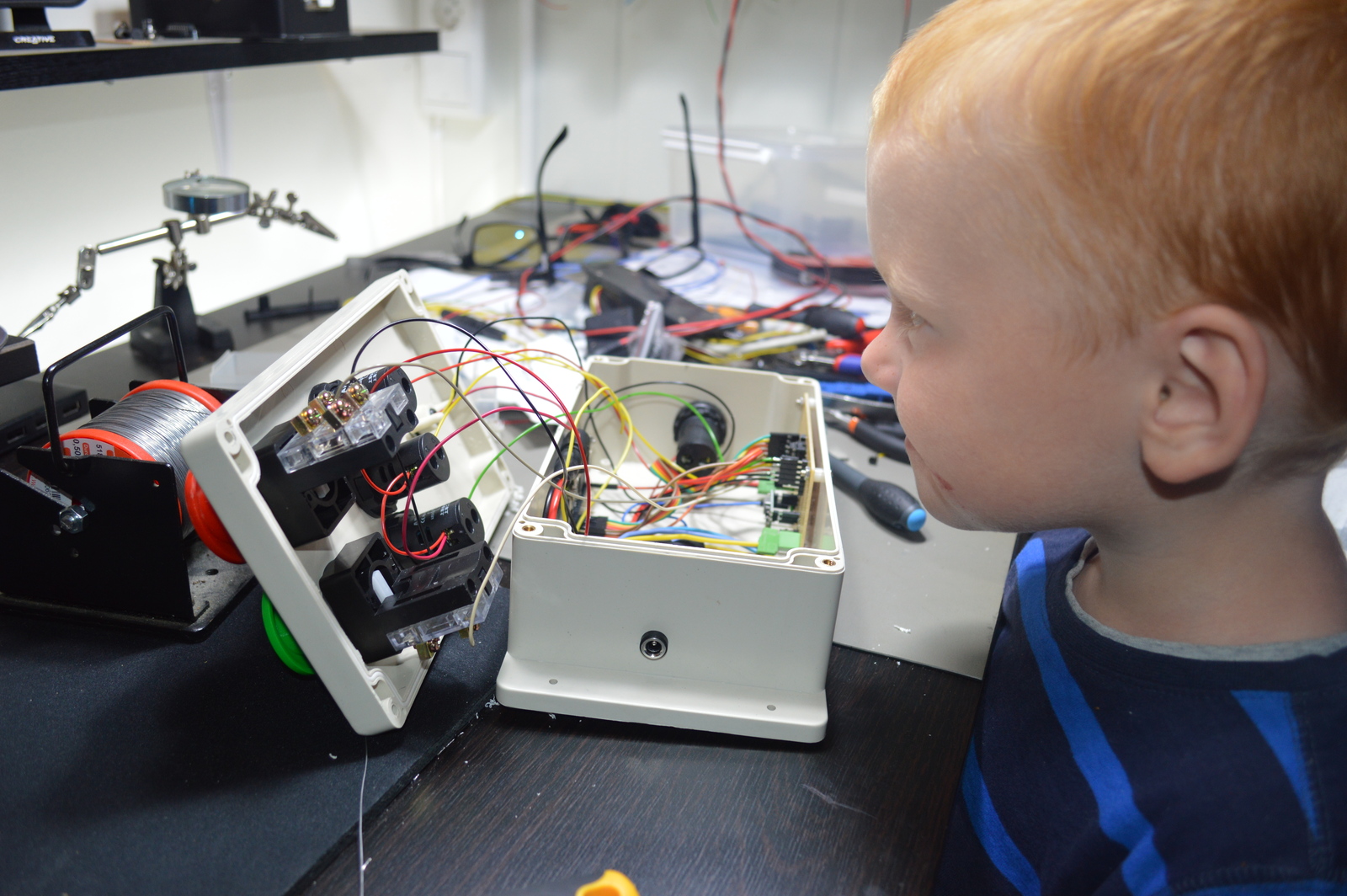
My boys inspected the build, and found it very interesting!
Operation
The function of the module is pretty simple, push the green button, and the strobe starts flashing, push the red, and it stops. If both buttons are held down at the same time — the buzzer sounds.
Of course the kids found the buzzer to be the most fun 😛
At the end of the build, I added a small push-button at the bottom of the module, that has a special function. When pressed — it shows whose turn it is to sleep in the top bunk. If green; Niklas and red; Alexander. The boys were always arguing who should sleep in the top bunk; this solved that argument elegantly.
In addition to the buttons, all functions on the alarm module can also be controlled wirelessly over MQTT.
Home Assistant
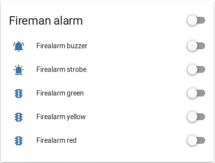
switch:
  - platform: mqtt
    name: "Firealarm strobe"
    state_topic: "node/gzl/strobe"
    command_topic: "node/gzl/strobe/set"
    payload_off: 0
    payload_on: 1
  - platform: mqtt
    name: "Firealarm buzzer"
    state_topic: "node/gzl/buzzer"
    command_topic: "node/gzl/buzzer/set"
    payload_off: 0
    payload_on: 1
  - platform: mqtt
    name: "Firealarm green"
    state_topic: "node/gzl/green"
    command_topic: "node/gzl/green/set"
    payload_off: 0
    payload_on: 1
  - platform: mqtt
    name: "Firealarm yellow"
    state_topic: "node/gzl/yellow"
    command_topic: "node/gzl/yellow/set"
    payload_off: 0
    payload_on: 1
  - platform: mqtt
    name: "Firealarm red"
    state_topic: "node/gzl/red"
    command_topic: "node/gzl/red/set"
    payload_off: 0
    payload_on: 1
Rotating whos turn it is to sleep in the top bunk is also controlled from Home Assistant, through an automation configuration.
- alias: Rotate kids top bunk Niklas
  trigger:
    - platform: time
      at: '05:00:00'
  condition:
    condition: state
    entity_id: sensor.top_bunk
    state: 'Alexander'
  action:
    service: mqtt.publish
    data_template:
      topic: "state/kids/top_bunk"
      retain: true
      payload: 'Niklas'

- alias: Rotate kids top bunk Alexander
  trigger:
    - platform: time
      at: '05:00:00'
  condition:
    condition: state
    entity_id: sensor.top_bunk
    state: 'Niklas'
  action:
    service: mqtt.publish
    data_template:
      topic: "state/kids/top_bunk"
      retain: true
      payload: 'Alexander'
Node ID
The node ID, gzl, is auto-generated by my logistics system, and it also stores associated identifiers, like MAC address, and location. This information is made available through an API, so any service I write can lookup the nodeID to figure out what, and where it is.
Software
The Python source is hosted on Github.
I/O
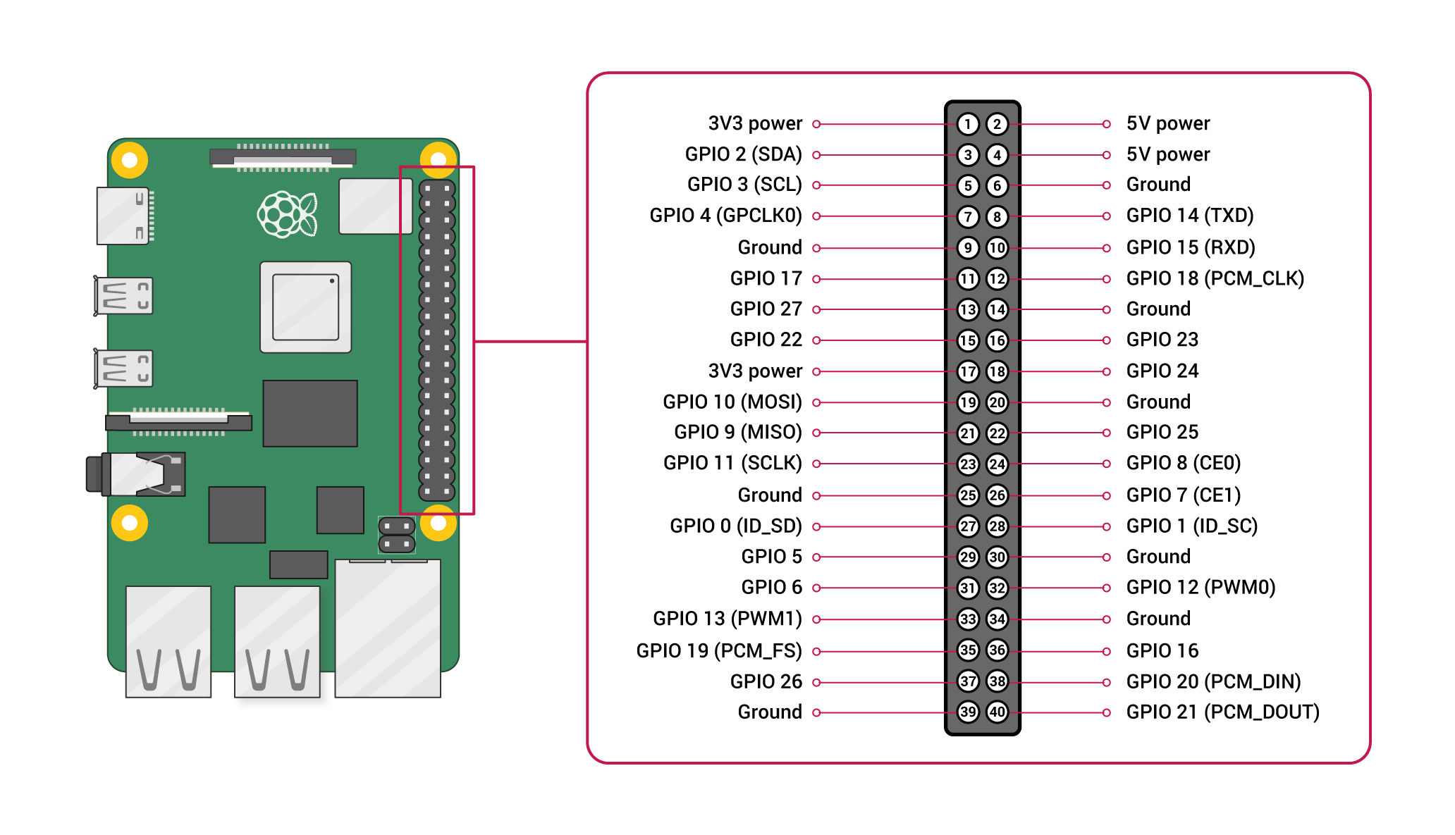
The pin-out numbering on the GPIO can be a bit confusing, I just picked pins physically located together.
Inputs
- GPIO16 Red push-button
- GPIO20 Green push-button
- GPIO21 Bottom push-button
Outputs
- GPIO5 Green panel indicator
- GPIO6 Yellow panel indicator
- GPIO13 Red panel indicator
- GPIO19 Blue strobe
- GPIO26 Buzzer
Schematic drawing
Parts
- 1 × AC adapter, 12 V=, 2 A, SMPS
- 1 × Darlington-driver, 7 step, ULN2003A, DIL16, In: 2.7K/5V
- 1 × DIL socket, 16-pin, 7.62mm
- 1 × Emergency light, LED strobe, Blue, 12V/24V, 2W/5W, 2 Hz
- 1 × Enclosure, plastic (waterproof), 200x120x75mm, flange
- 1 × Fuse 5x20 mm, 2.5 A, fast-acting
- 1 × Fuse holder, wire, 5x20 / 6.3x32mm
- 10 × Jump/dupont wire, female-female, 20cm, 2.54mm
- 1 × microSDHC card, Kingston, 16GB, class 10
- 1 × Panel buzzer with LED, Red, 12V, 22mm
- 1 × Panel LED indicator, Green, 12V, 22mm, AD16-22D/S
- 1 × Panel LED indicator, Red, 12V, 22mm, AD16-22D/S
- 1 × Panel LED indicator, Yellow, 12V, 22mm, AD16-22D/S
- 1 × PCB, stripboard prototyping, 94x53mm, 50cm2
- 1 × Power jack adapter, USB micro, right angle, 2.1mm x 5.5mm
- 1 × Power jack, panel, 2.1mm, plastic housing
- 1 × Power jack, w/wire, male, 2.1mm x 5.5mm
- 1 × Push-button, Green mushroom 38mm, 1 CO, 6A, 250VAC, on-(off)
- 1 × Push-button, Red mushroom 38mm, 1 CO, 6A, 250VAC, on-(off)
- 1 × Raspberry Pi Zero W, 1.0GHz, 512MB RAM, BT, WLAN
- 3 × Resistor, carbon film, 0.25W, 330 Ω, 5%
- 3 × Resistor, carbon film, 0.25W, 10 kΩ, 5%
- 8 × Spacer, round unthreaded, 3mm, Ø6mm, Delrin
- 16 × Straight pin header, female, Single row, 2.54mm
- 34 × Straight pin header, male, Single row, 2.54mm
- 1 × Switch, push-button, 1-pole, 1A, 50VAC, on-(off)
- 2 × Terminal block, pluggable, 3.5 mm, 2-pin screw female
- 2 × Terminal block, pluggable, 3.5 mm, 2-pin vertical male
- 2 × Terminal block, screw, 2.5 mm
- 1 × Voltage step-down buck converter, In: 7-28V, Out: 5V/3A
Last commit 2024-04-05, with message: Tag cleanup.