This post is part of the Rack Box Project series.
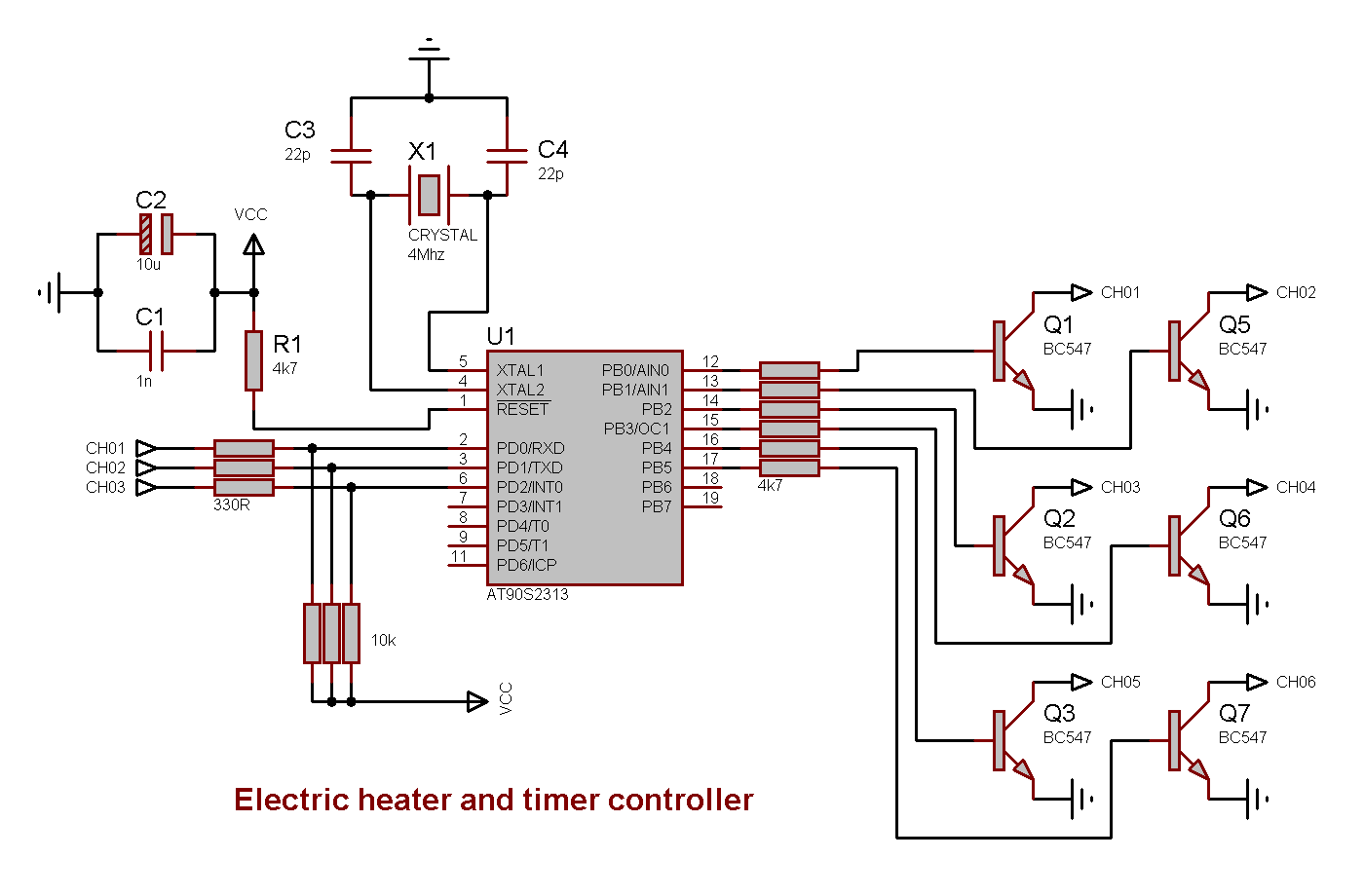
Controls an electric heater, and has a simple 15 minutes timer. Uses an AVR AT90S2313 microcontroller.
Table of contents
Details
- The module turns off the heat in the living room when the porch door has been open for 20 seconds. 90 seconds after the door has been closed; the heat is turned back on. The heat can also be disabled using an external switch.
- A short signal pulse from another module or a switch, will activate the output for 15 minutes. Used for turning on the test voltage on the Rack status panel. A new pulse within these 15 minutes turns the output off.
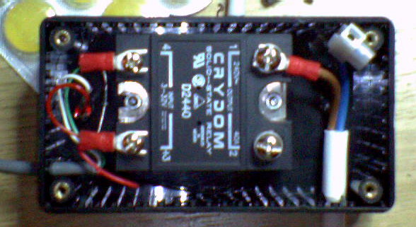
Leakage current
The solid state relay used for the heater, leaks a small amount of current, about 10mA. This can be eliminated using a resistor in parallel over the oven supply after the relay. A 22K, 5W resistor should be the job.
I/O
Inputs
- Porch door, from Multi-purpose module 1
- Manual oven disengage
- Signal activate
Outputs
- Oven relay N.O
- Oven relay N.C
- Oven LED
- Oven local LED
- Signal output
- Life-signal (to Module stability monitoring unit 2)
D-Sub 9-Pin
- Red: 5v
- Black: 0v
- Input: Porch door
- Input: Manual oven disengage
- Input: Signal activate
- Output: Oven relay N.O
- Output: Oven relay N.C
- Output: Oven LED
- Output: Signal
- Output: Life-signal
Source code
- Bascom-AVR source is available in a git repository:
- https://github.com/thomasjsn/AVR-Heater-and-timer-controller
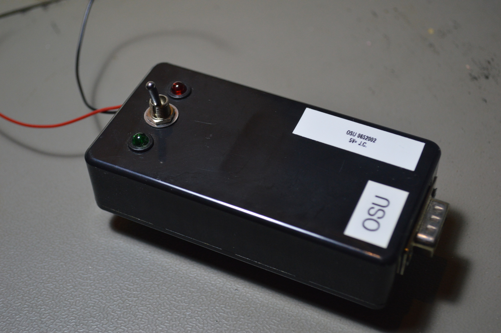
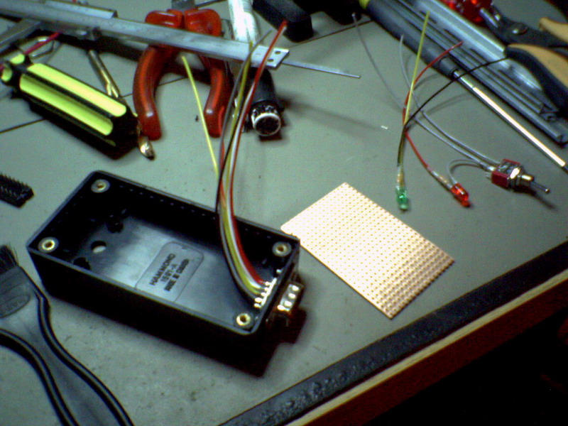
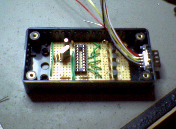
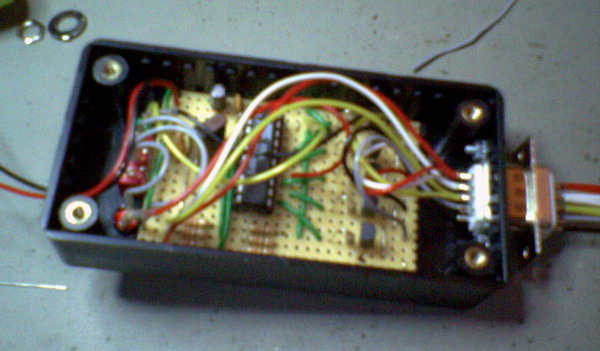
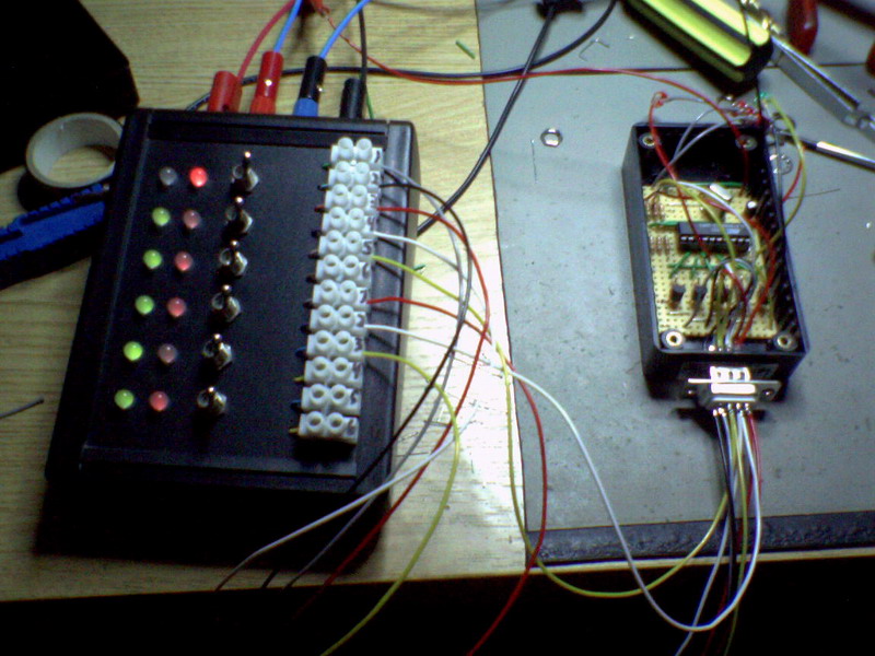
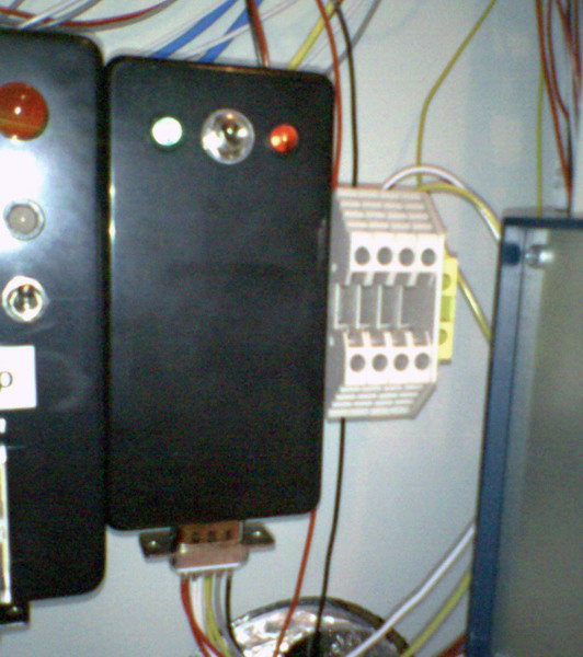
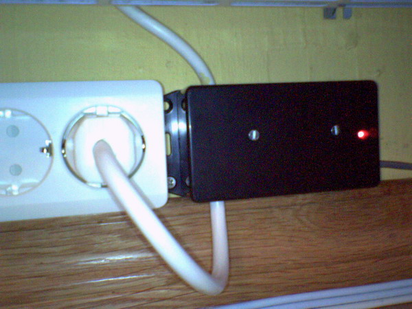
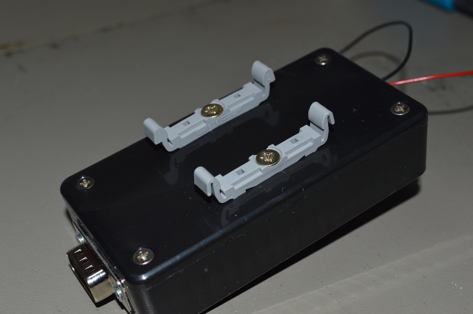
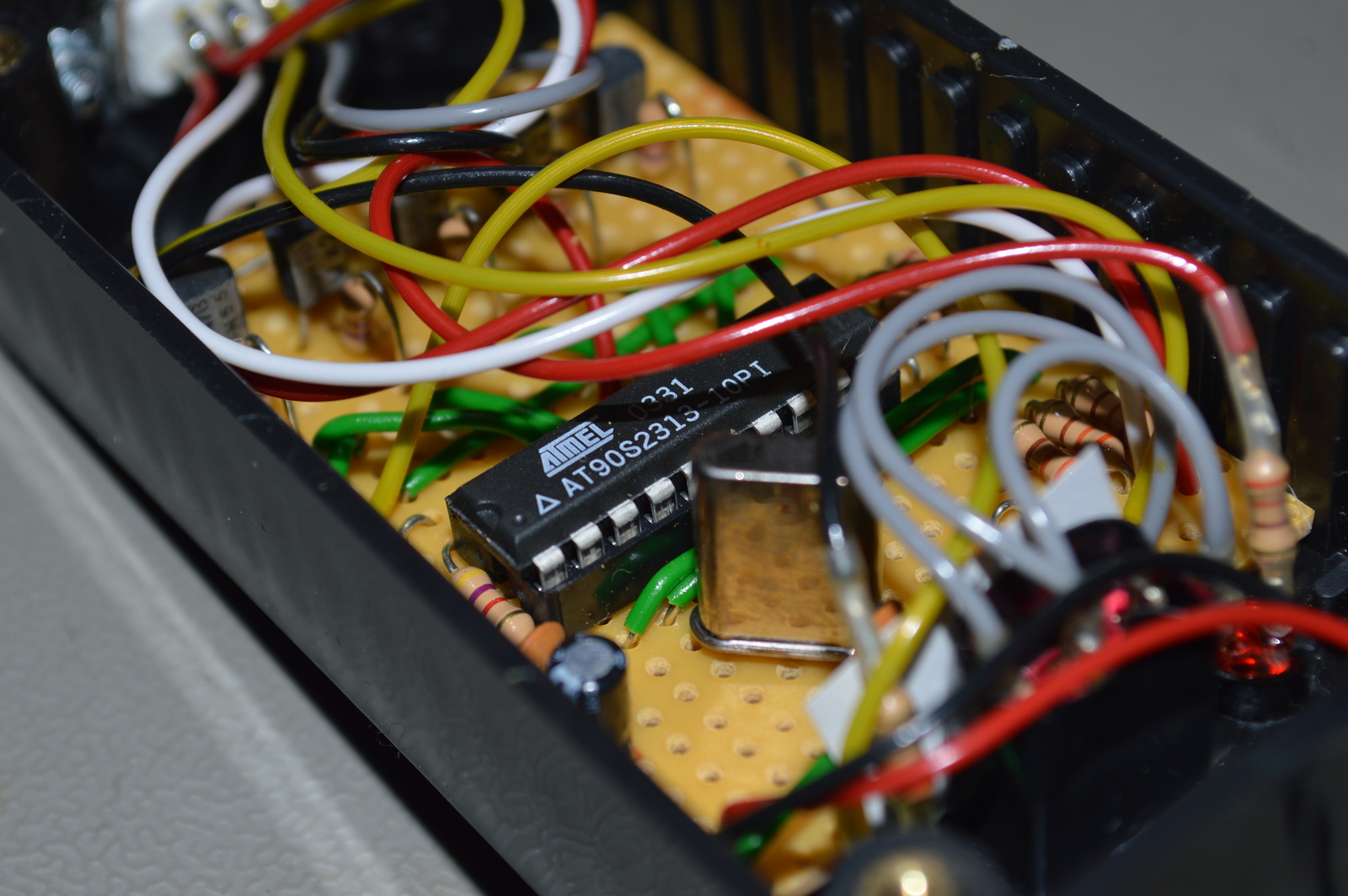
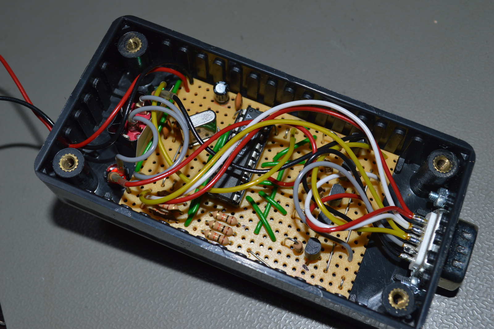
Photos
Schematic drawing
Parts list
- 1 × AVR AT90S2313-10PI, DIL-20, 10 MHz, 15 I/Os
- 1 × Capacitor, aluminium electrolytic, 10 µF, 25V
- 2 × Capacitor, ceramic, 22 pF, 100V
- 1 × Capacitor, ceramic, 1 nF, 100V
- 1 × D-sub soldering cups, 9 pin male
- 1 × DIL socket, 20-pin, 7.62mm
- 3 × Diode, small signal, 1N4148/Ph
- 1 × Enclosure, plastic (1591), 100x50x25mm
- 1 × LED 5mm coloured clear, Green, 2.1V, 20mA, 30mcd, 10°
- 1 × LED 5mm coloured clear, Red, 2.1V, 20mA, 8mcd, 10°
- 2 × LED holder 5mm, RTC51, black plastic
- 2 × Mounting bracket, DIN rail, Plastic
- 1 × Quartz crystal oscillator, 4 MHz
- 5 × Resistor, carbon film, 0.25W, 330 Ω, 5%
- 6 × Resistor, carbon film, 0.25W, 4.7 kΩ, 5%
- 3 × Resistor, carbon film, 0.25W, 10 kΩ, 5%
- 1 × Switch, toggle, 1-pole, micro, on-on
- 5 × Transistor, NPN, 100 mA, 45V, 0.5W, BC547B
Last commit 2023-02-05, with message: Add series for the rack box project.
Rack Box Project series
- Parallel port I/O module
- Power supply and fuse monitoring module, AVR
- Monitored fuse box, 6 channels
- Stack lights and horn controller — with AVR
- Mute and light controller for the Rack box — AVR module
- Monitored fuse box, 4 channels
- Module heartbeat monitor, 6 inputs — AVR
- Controller for lights and relays — AVR driven
- Emergency power off controller — controlled by 555 timers
- Fan controller with LCD — AVR powered
- Sound alarm control unit — AVR module
- Multiplexer output extender
- Multi-purpose AVR module
- Electric heater and timer controller — AVR
- Module heartbeat monitor, 15 inputs — LCD and AVR
- Serial port I/O module with 11 inputs — AVR
- Serial port I/O module with 9 in and outputs — AVR
- Serial interface for emergency power off — AVR
- Status panel for the Rack box project
- Intruder alarm system controller — AVR
- Serial port I/O module with 15 inputs — AVR
- Serial interface module, with analog and digital I/O — AVR
- The rack box project — an overview