This post is part of the Rack Box Project series.
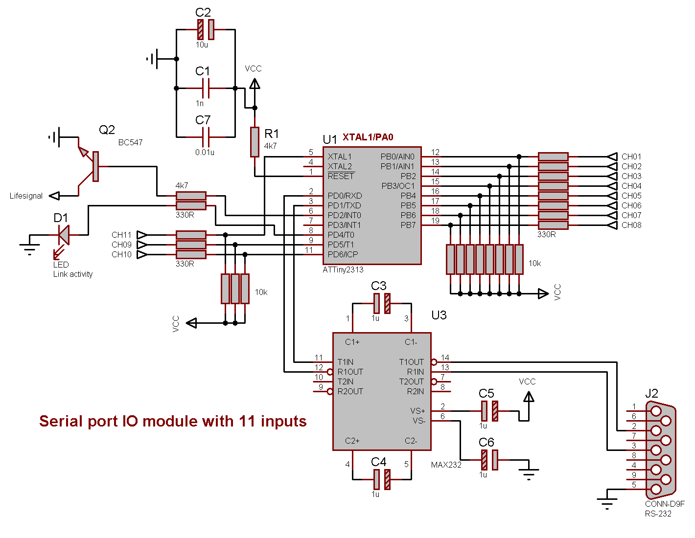
RS-232 input module, with 11 inputs. Rebuild of previous RS-485 module. Uses an AVR ATtiny2313 microcontroller.
Table of contents
Details
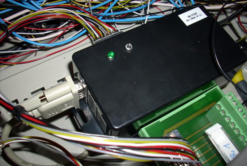
This I/O module is connected to the computer via the serial port. If the status on any of the 11 digital inputs changes; it will send a command string containing the module number, input number and new status. This also occurs on boot.
But — the module can not receive any commands, that makes it impossible to request an input status.
Noise and rebuild
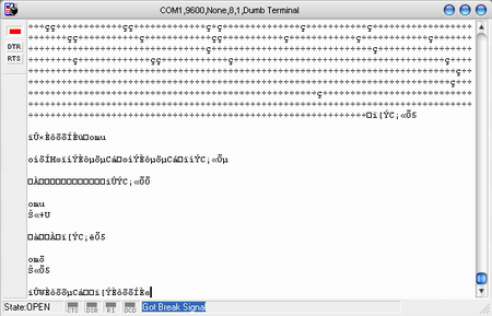
This module was originally designed for RS-485 — but, as the image shows, the signals were drowned in noise. Later I found out that the cause of the noise was a lack of stabilizing capacitors. 10 µF and 1 nF was installed directly over the AVR and the problem was solved.
It was then rebuild into RS-232, which is a bit easier to interact with then the RS-485. The source code was rewritten to suit the RS-232, but I ran out of flash memory I had to remove input 12. Leaving the module with only 11 inputs.
I/O
Inputs
- PB0 Input 1
- PB1 Input 2
- PB2 Input 3
- PB3 Input 4
- PB4 Input 5
- PB5 Input 6
- PB6 Input 7
- PB7 Input 8
- PD5 Input 9
- PD6 Input 10
- PA0 Input 11
Outputs
- PD2 Life-signal
- PD3 RS-485 Send enable (not in use)
- PD4 Link activity LED
Interface
- PD0 RS-232 Rx
- PD1 RS-232 Tx
Connectors
15-pin
- 5v
- 0v
- Input 1
- Input 2
- Input 3
- Input 4
- Input 5
- Input 6
- Input 7
- Input 8
- Input 9
- Input 10
- Input 11
- Life-signal
9-pin
- 2 Transmit
- 3 Receive
- 5 GND
Communication
Interfacing is done with RS-232, using MAX232 or MAX202 and the SIOS protocol.
001:s:00:1:125 'boot
001:i:02:1:116 'input 2 on
001:i:01:1:115 'input 1 on
001:i:02:0:116 'input 2 off
001:i:01:0:115 'input 1 off
001:s:01:1:126 'life-signal
Serial settings
- Baud: 9600
- Data bits: 7
- Parity: None
- Stop bits: 1
Source code
- Bascom-AVR source is available in a git repository:
- https://github.com/thomasjsn/AVR-Online-monitoring-unit/tree/v1.1
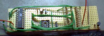
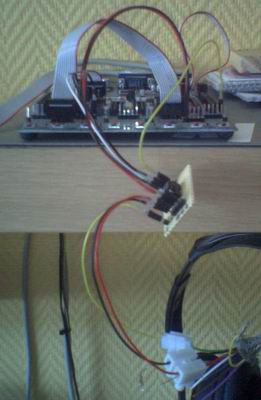
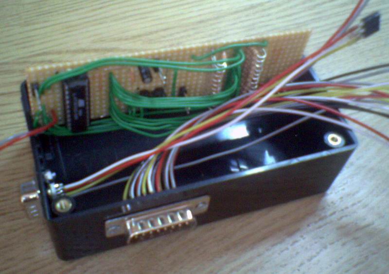
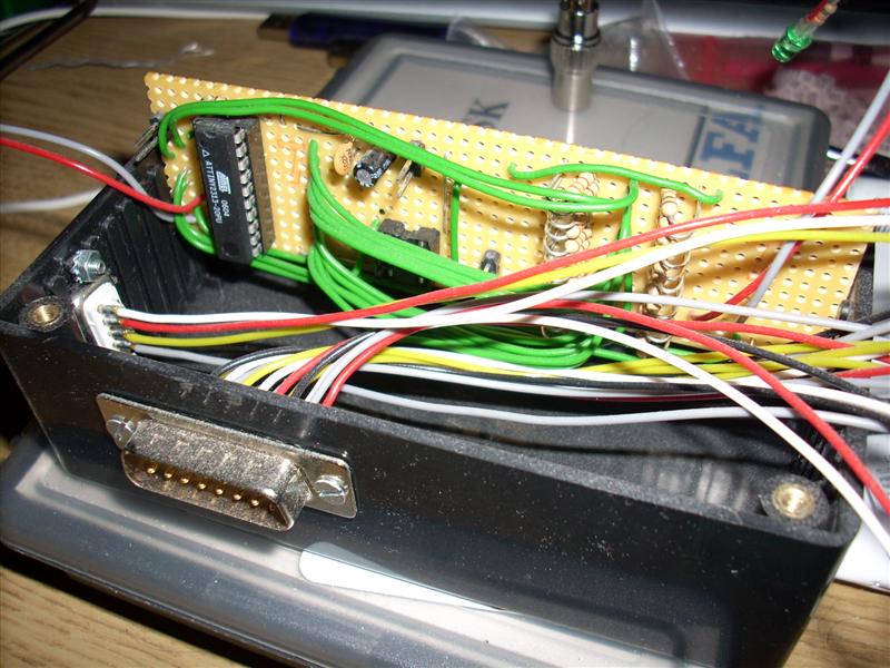
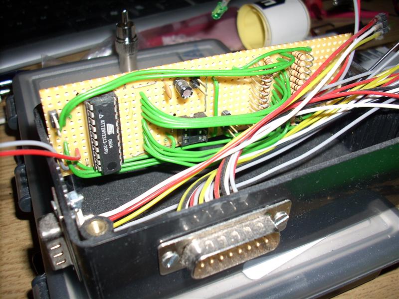
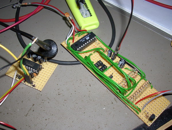
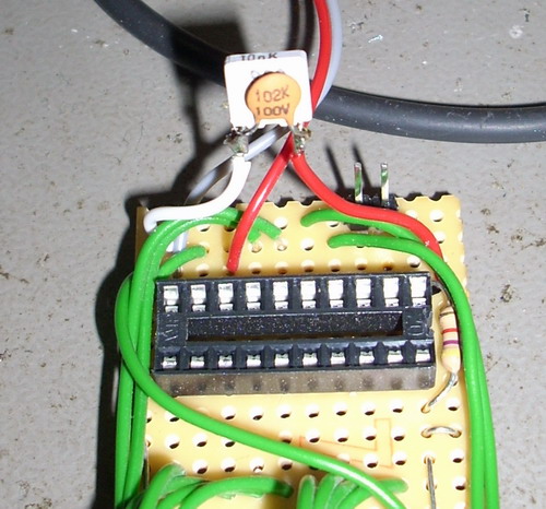
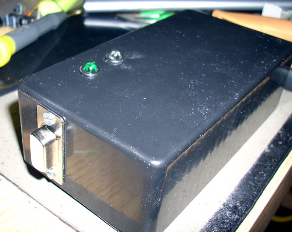
Photos

Schematic drawing
Parts list
- 1 × AVR ATtiny2313-20PU, DIL-20, 20 MHz, 18 I/Os
- 5 × Capacitor, aluminium electrolytic, 1 µF, 50V
- 2 × Capacitor, aluminium electrolytic, 10 µF, 25V
- 1 × Capacitor, aluminium electrolytic, 47 µF, 25V
- 2 × Capacitor, ceramic, 1 nF, 100V
- 2 × Capacitor, metallized polyester foil, 10 nF, (0.01 µF)
- 1 × D-sub soldering cups, 15 pin male
- 1 × D-sub soldering cups, 9 pin female
- 1 × DIL socket, 16-pin, 7.62mm
- 1 × DIL socket, 20-pin, 7.62mm
- 1 × Enclosure, plastic (1591 FL), 120x65x40mm, flange
- 1 × Fuse 5x20 mm, 200 mA, fast-acting
- 1 × Fuse holder, open, PCB, 5x20mm
- 1 × Fuse holder, open, PCB, Protective cover
- 1 × LED 5mm clear, Yellow, 2.0V, 20mA, 250mcd, 6°
- 1 × LED 5mm coloured clear, Green, 2.1V, 20mA, 30mcd, 10°
- 2 × LED holder 5mm, RTC51, black plastic
- 2 × Mounting bracket, DIN rail, Plastic
- 32 cm2 PCB, stripboard, 100x160mm, 160cm2
- 13 × Resistor, carbon film, 0.25W, 330 Ω, 5%
- 2 × Resistor, carbon film, 0.25W, 4.7 kΩ, 5%
- 11 × Resistor, carbon film, 0.25W, 10 kΩ, 5%
- 1 × RS232 interface, MAX232CPE, dual
- 11 × Straight pin header, female, Single row, 2.54mm
- 14 × Straight pin header, male, Single row, 2.54mm
- 1 × Transistor, NPN, 100 mA, 45V, 0.5W, BC547B
Last commit 2024-04-05, with message: Tag cleanup.
Rack Box Project series
- Parallel port I/O module
- Power supply and fuse monitoring module, AVR
- Monitored fuse box, 6 channels
- Stack lights and horn controller — with AVR
- Mute and light controller for the Rack box — AVR module
- Monitored fuse box, 4 channels
- Module heartbeat monitor, 6 inputs — AVR
- Controller for lights and relays — AVR driven
- Emergency power off controller — controlled by 555 timers
- Fan controller with LCD — AVR powered
- Sound alarm control unit — AVR module
- Multiplexer output extender
- Multi-purpose AVR module
- Electric heater and timer controller — AVR
- Module heartbeat monitor, 15 inputs — LCD and AVR
- Serial port I/O module with 11 inputs — AVR
- Serial port I/O module with 9 in and outputs — AVR
- Serial interface for emergency power off — AVR
- Status panel for the Rack box project
- Intruder alarm system controller — AVR
- Serial port I/O module with 15 inputs — AVR
- Serial interface module, with analog and digital I/O — AVR
- The rack box project — an overview