This post is part of the Rack Box Project series.
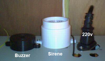
Simple unit to control three sound signals; beep, siren and buzzer. Uses an AVR ATtiny2313 microcontroller.
Table of contents
Details
This simple unit controls three sound signals; beep, siren and buzzer. Each sound signal will only be given once; when a new alarm is triggered. The input must remain clear for at least four seconds for that signal to rearm.
A beep is given every six minutes if an alarm is active, as a reminder. The sound LED flashes when a sound alarm is active; once for signal 1 (beep), twice for signal 2 (siren) and three times for signal 3 (buzzer), this flashing pattern is repeated.
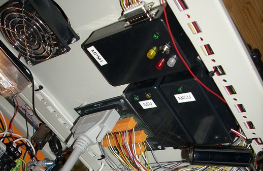
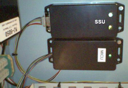
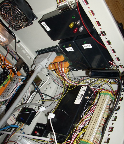
This module used to control the sound alarms in the Rack box. Modules with alarm outputs sent a signal to this sound controller, which carried out the sound alarm. If system mute was active the power to the buzzer and siren was disconnected.
Signals
- 100 ms siren
- One second siren
- Three seconds buzzer
I/O
Inputs
- Signal: Beep
- Signal: Siren pulse
- Signal: Buzzer pulse
Outputs
- Siren
- Buzzer
- Sound LED
- Life-signal to Module heartbeat monitor
D-Sub 9-pin
- 0v
- 5v
- Signal: Beep
- Signal: Siren pulse
- Signal: Buzzer pulse
- Siren
- Buzzer
- Sound LED
- Life-signal
Source code
- Bascom-AVR source is available in a git repository:
- https://github.com/thomasjsn/AVR-Sound-alarm-controller
Photos
Schematic drawing
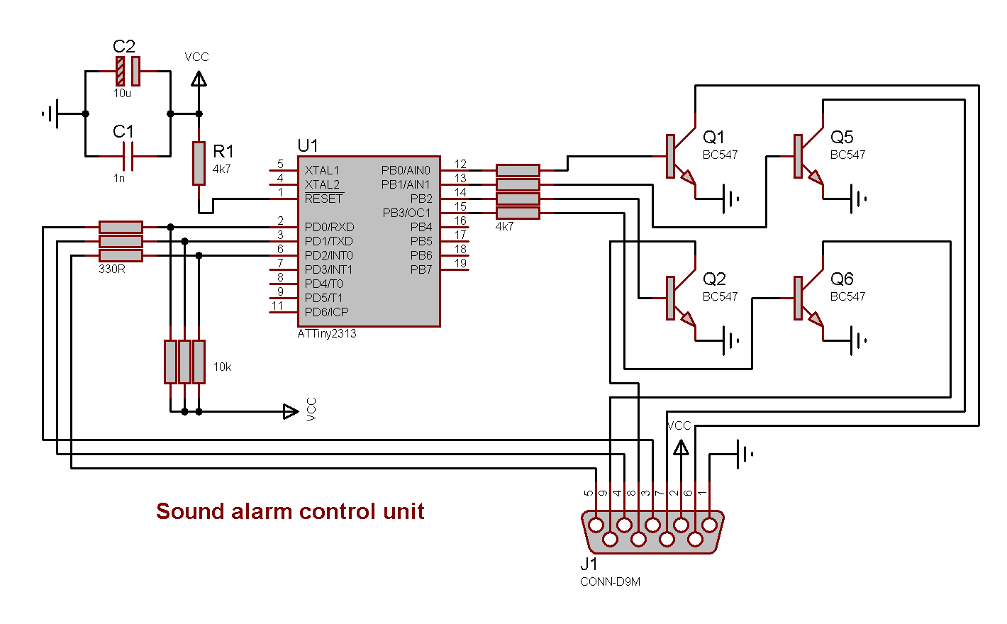
Parts list
- 1 × AVR ATtiny2313-20PU, DIL-20, 20 MHz, 18 I/Os
- 1 × Capacitor, aluminium electrolytic, 10 µF, 25V
- 1 × Capacitor, ceramic, 1 nF, 100V
- 1 × D-sub soldering cups, 9 pin male
- 1 × DIL socket, 20-pin, 7.62mm
- 1 × Enclosure, plastic (1591 FL), 100x50x25mm, flange
- 1 × LED 5mm coloured clear, Green, 2.1V, 20mA, 30mcd, 10°
- 1 × LED 5mm coloured clear, Yellow, 2.0V, 20mA, 40mcd, 10°
- 2 × LED holder 5mm, RTC51, black plastic
- 32 cm2 PCB, stripboard, 100x160mm, 160cm2
- 5 × Resistor, carbon film, 0.25W, 330 Ω, 5%
- 5 × Resistor, carbon film, 0.25W, 4.7 kΩ, 5%
- 3 × Resistor, carbon film, 0.25W, 10 kΩ, 5%
- 4 × Transistor, NPN, 100 mA, 45V, 0.5W, BC547B
Last commit 2023-02-05, with message: Add series for the rack box project.
Rack Box Project series
- Parallel port I/O module
- Power supply and fuse monitoring module, AVR
- Monitored fuse box, 6 channels
- Stack lights and horn controller — with AVR
- Mute and light controller for the Rack box — AVR module
- Monitored fuse box, 4 channels
- Module heartbeat monitor, 6 inputs — AVR
- Controller for lights and relays — AVR driven
- Emergency power off controller — controlled by 555 timers
- Fan controller with LCD — AVR powered
- Sound alarm control unit — AVR module
- Multiplexer output extender
- Multi-purpose AVR module
- Electric heater and timer controller — AVR
- Module heartbeat monitor, 15 inputs — LCD and AVR
- Serial port I/O module with 11 inputs — AVR
- Serial port I/O module with 9 in and outputs — AVR
- Serial interface for emergency power off — AVR
- Status panel for the Rack box project
- Intruder alarm system controller — AVR
- Serial port I/O module with 15 inputs — AVR
- Serial interface module, with analog and digital I/O — AVR
- The rack box project — an overview