This post is part of the Rack Box Project series.
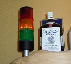
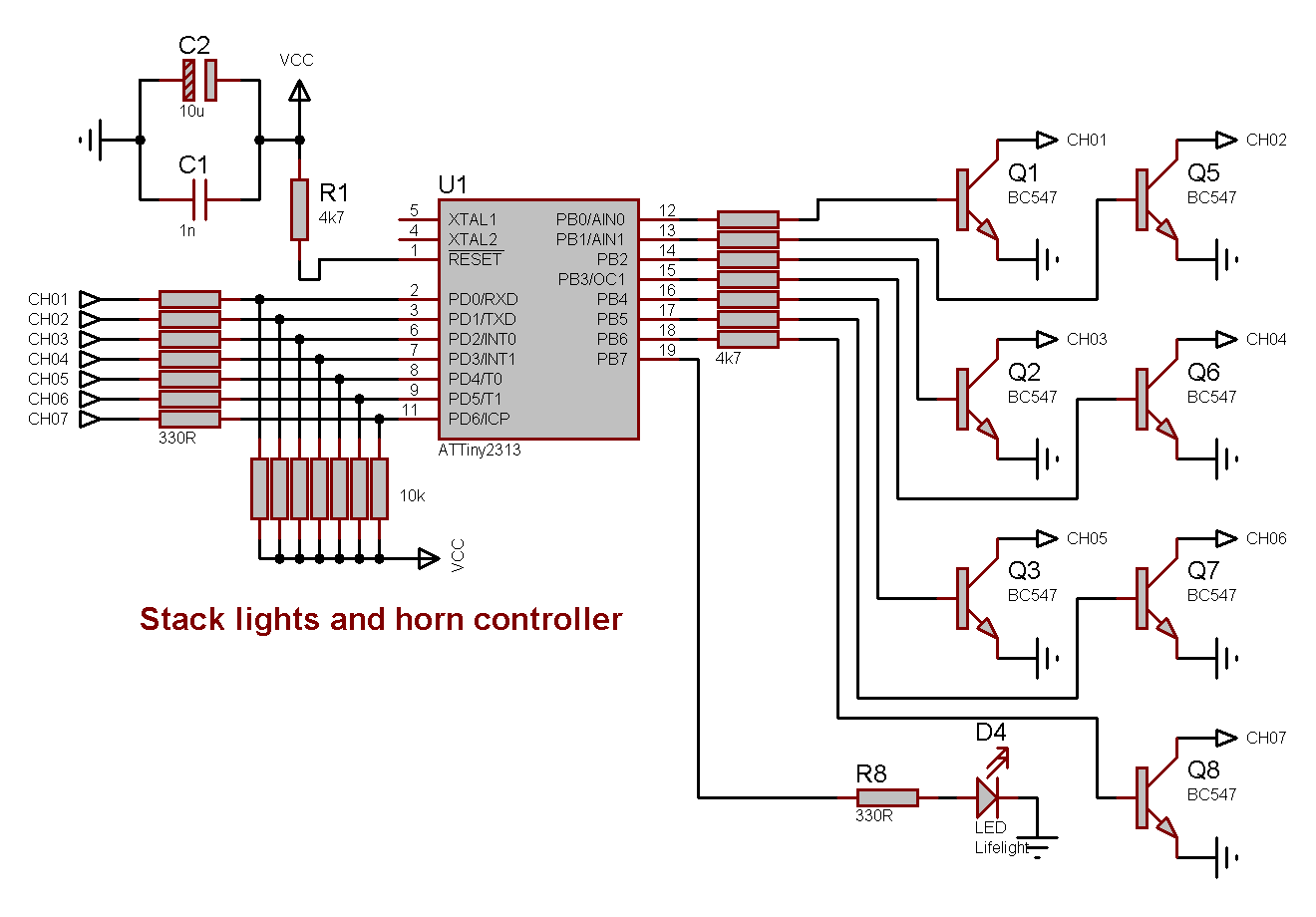
A control module for a green, yellow and red stack light, and signalling horn. Uses an AVR ATtiny2313 microcontroller.
Table of contents
Details
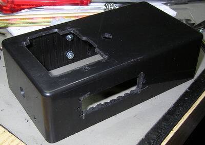
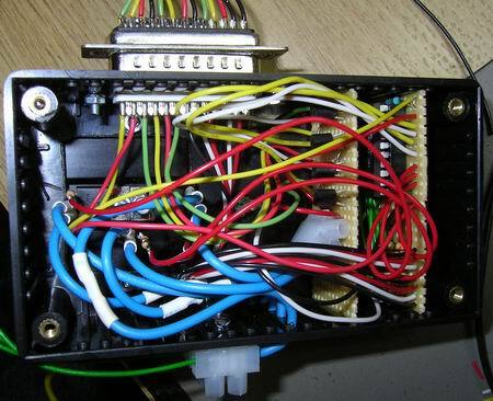
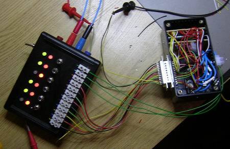
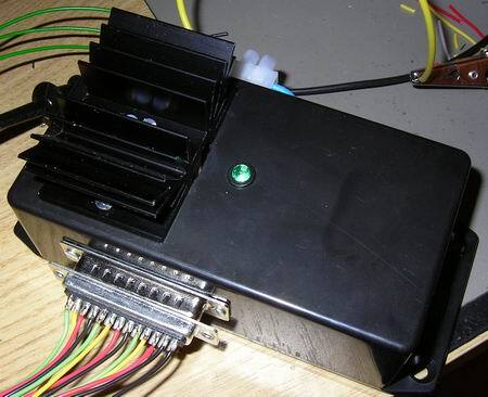
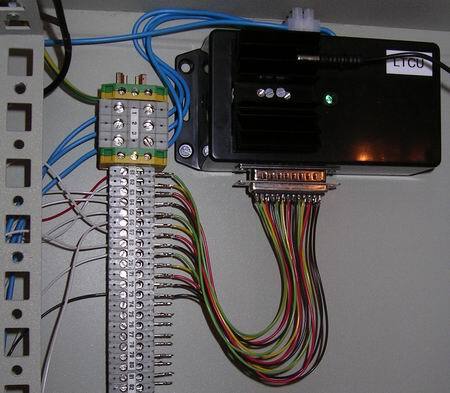
This is the rack box alarm handling unit. It controls the stack light, strobes and horn. Six different signals can be displayed, depending on the alarm situation. If mute is active; no signals is given. The power transistors for the stack light used to be located inside the module, hence the heat-sink. They have been moved to a separate power transistor unit.
Video
Signals
| Situation | Green | Yellow | Red | Strobe | Horn |
|---|---|---|---|---|---|
| Flashing | 0.1 | ||||
| Rack temp | Steady | Flashing | Yellow | 1 s | |
| SIOS alarm | Flashing | Yellow | 1 s | ||
| Serial offline | Flashing | Steady | Yellow | 1 s ⭐ | |
| Module offline | Steady | Flashing | Red | 1 s ⭐ | |
| Supply error | Flashing | Red | 1 s ⭐ |
⭐ 0.1 s when muted
I/O
Inputs
- Signal 1
- Signal 2
- Signal 3
- Signal 4
- Signal 5
- Signal 6
- Mute
Outputs
- Stack light green
- Stack light yellow
- Stack light red
- Strobe yellow
- Strobe red
- Horn
- Life-signal (to Module stability monitoring unit 2)
- Life-light
D-Sub 25-pin
- +5V
- 0V
- Strobe yellow
- Strobe red
- Horn
- Life-signal
- Signal 1
- Signal 2
- Signal 3
- Signal 4
- Signal 5
- Signal 6
- Mute signal
- Stack light green
- Stack light yellow
- Stack light red
Source code
- Bascom-AVR source is available in a git repository:
- https://github.com/thomasjsn/AVR-Stack-lights-controller
Photos
Schematic drawing
Parts used
- 1 × AVR ATtiny2313-20PU, DIL-20, 20 MHz, 18 I/Os
- 1 × Capacitor, aluminium electrolytic, 10 µF, 25V
- 2 × Capacitor, ceramic, 22 pF, 100V
- 1 × Capacitor, ceramic, 1 nF, 100V
- 1 × D-sub soldering cups, 25 pin male
- 1 × DIL socket, 20-pin, 7.62mm
- 1 × Enclosure, plastic (1591 FL), 120x65x40mm, flange
- 1 × Fuse 5x20 mm, 400 mA, fast-acting
- 1 × Fuse holder, open, PCB, 5x20mm
- 1 × Fuse holder, open, PCB, Protective cover
- 1 × Heatsink, 6K/W @ 10W, 37.5mm 49g
- 1 × LED 5mm coloured clear, Green, 2.1V, 20mA, 30mcd, 10°
- 1 × LED 5mm, Green, 2.0V, 10mA
- 1 × LED 5mm, Orange, 2.0V, 20mA
- 1 × LED 5mm, Red, 2.0V, 20mA
- 1 × LED holder 5mm, RTC51, black plastic
- 96 cm2 PCB, stripboard, 100x160mm, 160cm2
- 1 × Quartz crystal oscillator, 4 MHz
- 11 × Resistor, carbon film, 0.25W, 330 Ω, 5%
- 8 × Resistor, carbon film, 0.25W, 4.7 kΩ, 5%
- 7 × Resistor, carbon film, 0.25W, 10 kΩ, 5%
- 7 × Transistor, NPN, 100 mA, 45V, 0.5W, BC547B
Last commit 2023-02-05, with message: Add series for the rack box project.
Rack Box Project series
- Parallel port I/O module
- Power supply and fuse monitoring module, AVR
- Monitored fuse box, 6 channels
- Stack lights and horn controller — with AVR
- Mute and light controller for the Rack box — AVR module
- Monitored fuse box, 4 channels
- Module heartbeat monitor, 6 inputs — AVR
- Controller for lights and relays — AVR driven
- Emergency power off controller — controlled by 555 timers
- Fan controller with LCD — AVR powered
- Sound alarm control unit — AVR module
- Multiplexer output extender
- Multi-purpose AVR module
- Electric heater and timer controller — AVR
- Module heartbeat monitor, 15 inputs — LCD and AVR
- Serial port I/O module with 11 inputs — AVR
- Serial port I/O module with 9 in and outputs — AVR
- Serial interface for emergency power off — AVR
- Status panel for the Rack box project
- Intruder alarm system controller — AVR
- Serial port I/O module with 15 inputs — AVR
- Serial interface module, with analog and digital I/O — AVR
- The rack box project — an overview