This post is part of the Rack Box Project series.
A desk panel box full of LEDs, buttons and switches. Built for the rack box project.
Table of contents
Details
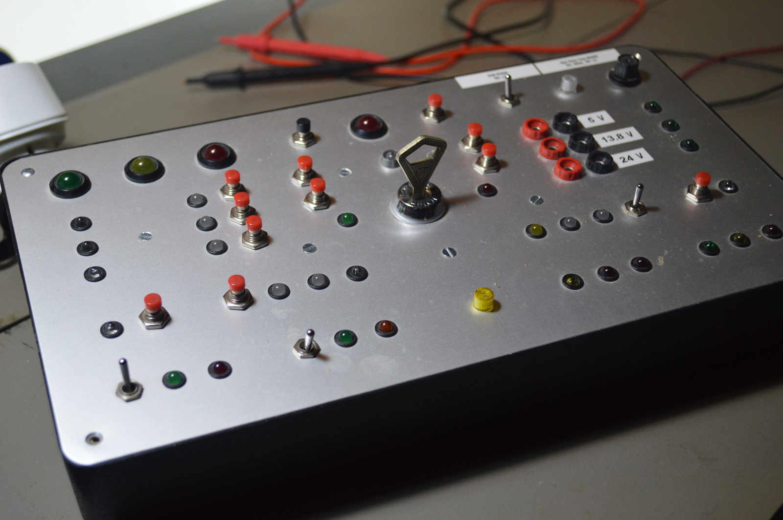
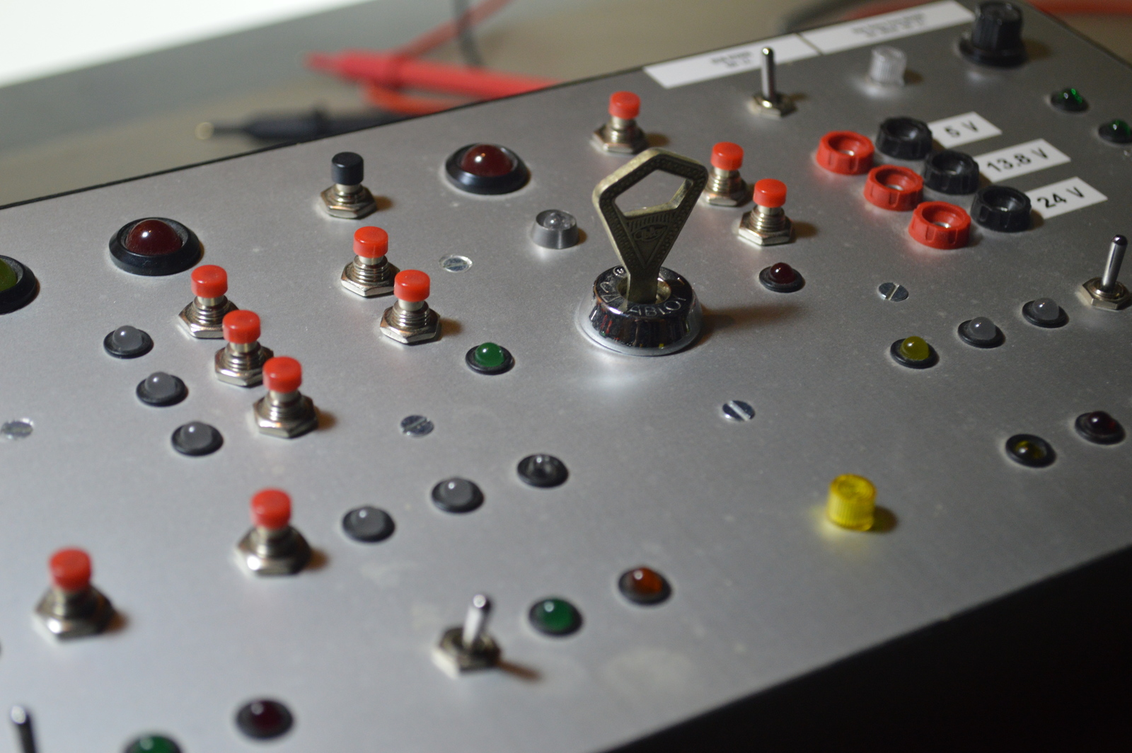
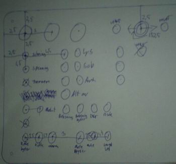
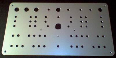
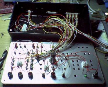
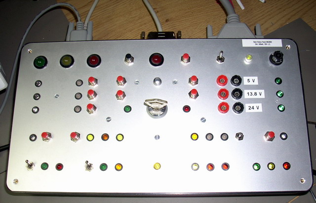
To get a sense of that was happening in the rack box, and to be able to manually control stuff, I built a status panel that I had on my desk in the old apartment.
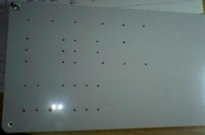
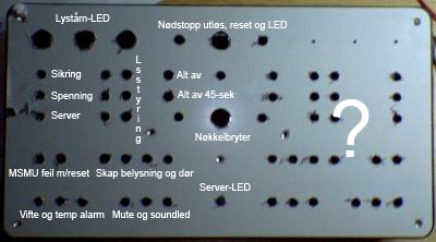
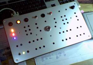
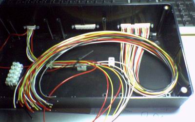
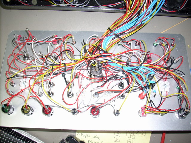
It had LEDs, push-buttons and switches for pretty much everything in the rack box; lights, alarms, fan, mute etc. It was made of a desk box with an aluminium front plate, which made it pretty sturdy.
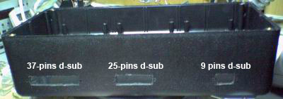
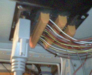
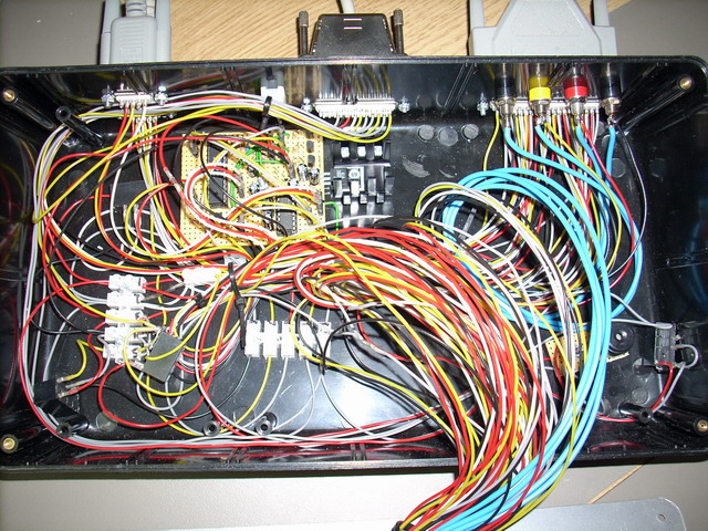
The panel connected to the rack box project with three D-sub cables; 9, 25 and 37 pins. If any of these cables were disconnected or the panel fuse burned out, a monitoring alarm would sound.
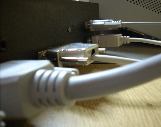
There was also a microcontroller module inside the panel, controlling a few LEDs, switches and the emergency control. This was connected to my computer with a serial cable.
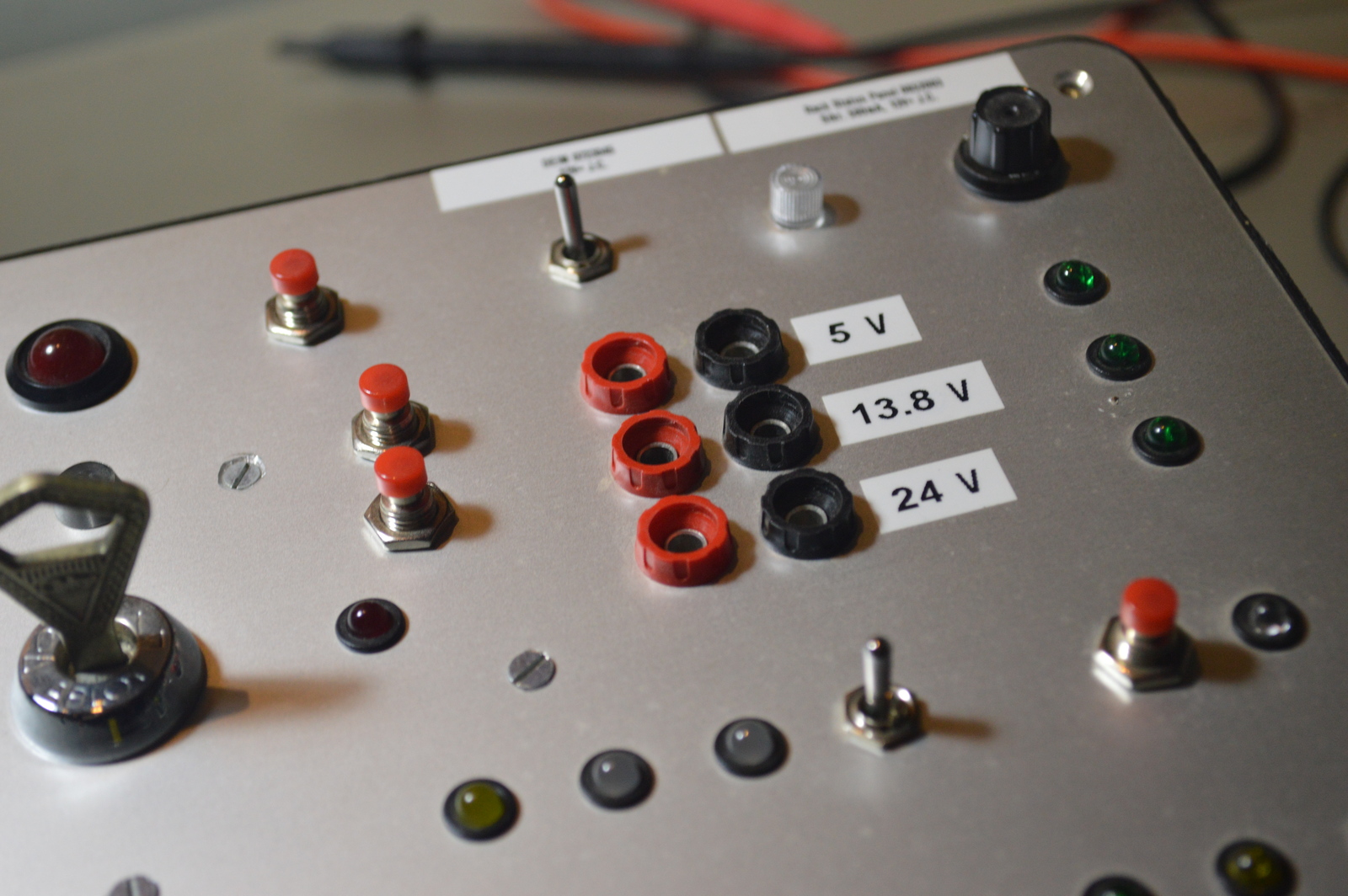
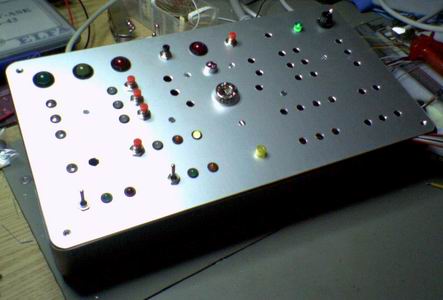
The voltage levels in the rack (5, 13.8 and 24) were available through lab plugs, pretty handy when testing stuff. They had a dedicated automatic fuse, so not to take the whole rack box down in case of a short.
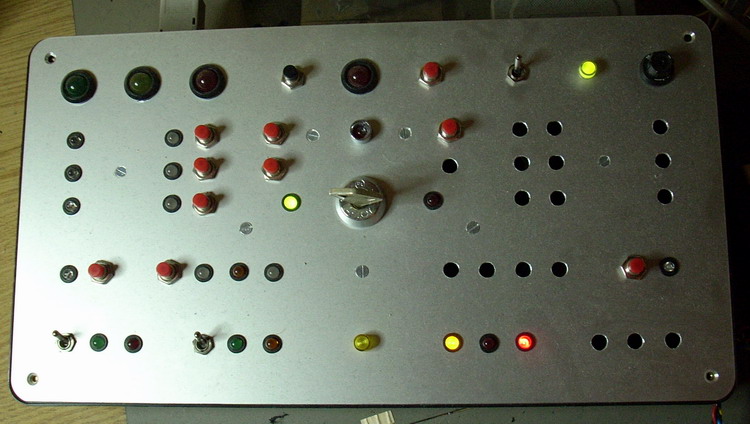
The panel had three states;
- On, all LEDs, buttons and switches worked.
- Off, all buttons and switches worked, but the LEDs were turned off.
- Disabled, all LEDs were turned off, buttons and switches were disabled.
At the center of the panel was a key switched, used to arm and disarm the intruder alarm. When the intruder alarm was armed the panel went into the disabled state. The emergency stop could also be triggered, and reset, from this panel.
This status panel was very analog and not something I would have built today, but in 2006/2007 it wasn’t as easy to get a fancy dashboard on the computer as it is today. Just doing changes to this panel was pretty tricky and time consuming… Today one can just use something like Home Assistant.
Connectors
Internal
- 12v +
- 12v -
- Emergency shutdown +
- Emergency shutdown -
- Emergency shutdown reset to relay
- Emergency shutdown reset to Emergency shutdown unit
- Emergency shutdown trigger to Emergency shutdown unit
- Emergency shutdown LED from Emergency shutdown unit
- Life-signal from Digital emergency interface module to Module stability monitoring unit 2
- 12v -
9-pin
- Stack lights green (Signal and lights controlling unit)
- Rack temp alarm (Fan and temperature unit)
- Stack lights yellow (Signal and lights controlling unit)
- Rack fan (Fan and temperature unit)
- 12v +
- Supply error (Main monitoring unit)
- Stack lights red (Signal and lights controlling unit)
- Serial Server timeout (Main monitoring unit)
- Fuse error (Main monitoring unit)
25-pin
- Deactivate emergency shutdown strobe (Emergency shutdown unit)
- Buzzer
- Activate panel
- Panel active
- Life-signal from Digital emergency interface module to Module stability monitoring unit 2
- Oven disengaged LED (Oven and signal unit)
- Porch door LED (Multi-purpose module 1)
- Light sensor (Light sensor)
- Test voltage on/off
- Return - (to Multi-purpose module 1)
37-pin
- 12v -
- Module error LED
- Mute LED (Mute and illumination controlling unit)
- Amber LED (not connected in rack)
- Low voltage, yellow LED
- Rack box door (Mute and illumination controlling unit)
- Rack box lights (Mute and illumination controlling unit)
- Light control unit 3 LED
- Light control unit 2 LED
- Light control unit 1 LED
- Light control unit 3 Switch
- Light control unit 2 Switch
- Light control unit 1 Switch
- Rack box lights switch (Mute and illumination controlling unit)
- System mute switch (Mute and illumination controlling unit)
- Fan switch (Fan and temperature unit)
- Emergency shutdown unit +
- Emergency shutdown unit -
- Emergency shutdown unit Trigger
- Emergency shutdown unit LED
- Emergency shutdown unit Reset
- Alarm LED
- Panel error LED (Multi-purpose module 1)
- Key switch N.C
- Key switch N.O
- Return + (to Multi-purpose module 1)
- Button by blue LED
- Light control unit lights out 45 sec
- Light control unit auto light
- Green center LED
- Red center LED
- Oven disengaged manually (Oven and signal unit)
- IR sensor 1 LED (Multi-purpose module 1)
- Red LED (Not connected in rack)
- Lights living room off (Multi-purpose module 1)
- Module stability monitoring unit 2 Reset
- Module stability monitoring unit 2 LED
Photos
Parts list
- 2 × Banana plug, 4mm black
- 1 × Banana plug, 4mm red
- 1 × Banana plug, 4mm yellow
- 3 × Banana socket, panel, 563/2, 4mm black
- 3 × Banana socket, panel, 563/2, 4mm red
- 1 × Banana socket, panel, BIL 20, 4mm black
- 1 × Banana socket, panel, BIL 20, 4mm blue
- 1 × Banana socket, panel, BIL 20, 4mm red
- 1 × Banana socket, panel, BIL 20, 4mm yellow
- 1 × Buzzer, electromagnetic PCB, 12V, 35mA, Ø16mm, int. oscillator
- 6 × Cable tie mount, screw, 5.1 mm, White
- 1 × D-sub soldering cups, 25 pin male
- 1 × D-sub soldering cups, 37 pin male
- 1 × D-sub soldering cups, 9 pin male
- 4 × Diode, rectifier, 1 A, 400V, 1N4004
- 1 × Diode, small signal, 1N4148/Ph
- 1 × Fuse 5x20 mm, 500 mA, fast-acting
- 1 × Fuse holder, panel, 5x20mm, 345511
- 1 × LED 10mm, Green, 2.2V, 20mA
- 2 × LED 10mm, Red, 2.0V, 20mA
- 1 × LED 10mm, Yellow, 2.1V, 20mA
- 3 × LED 5mm clear, Blue, 4.9V, 20mA, 350mcd, 12°
- 1 × LED 5mm clear, Red, 2.0V, 20mA, 140mcd, 6°
- 2 × LED 5mm clear, Yellow, 2.0V, 20mA, 250mcd, 6°
- 4 × LED 5mm coloured clear, Green, 2.1V, 20mA, 30mcd, 10°
- 3 × LED 5mm coloured clear, Red, 2.1V, 20mA, 8mcd, 10°
- 3 × LED 5mm coloured clear, Yellow, 2.0V, 20mA, 40mcd, 10°
- 3 × LED 5mm, Green, 2.0V, 10mA
- 1 × LED 5mm, Orange, 2.0V, 20mA
- 2 × LED 5mm, Red, 2.0V, 20mA
- 8 × LED 5mm, Red/Green, 2.0 2.1V, 10mA, 100 63mcd, 30°
- 1 × LED 5mm, Yellow, 2.0V, 25mA
- 4 × LED holder 10mm, Black plastic
- 29 × LED holder 5mm, RTC51, black plastic
- 1 × LED lamp 5mm, Red, Ø8.0mm, 12V, 20mA, 15mcd
- 1 × LED lens 5mm, CLF 280, Clear
- 1 × LED lens 5mm, CLF 280, Yellow
- 1 × Panel case, sloped, graphite grey, 308x167mm with alu. lid
- 4 × Relay, 2 CO, HJR1-2C, 12 VDC, 1A 120V, PCB
- 6 × Resistor, carbon film, 0.25W, 330 Ω, 5%
- 30 × Resistor, metal film, 0.6W, 1 kΩ, 1%
- 1 × Resistor, metal film, 0.6W, 2.2 kΩ, 1%
- 1 × Spacer, round unthreaded, 3mm, Ø6mm, Delrin
- 1 × Switch, key-operated, 2 positions, 19mm, latch
- 11 × Switch, push-button, 1-pole, 1A, 50VAC, off-(on)
- 1 × Switch, push-button, 1-pole, 1A, 50VAC, on-(off)
- 1 × Switch, toggle, 1-pole, micro, (on)-off-(on)
- 1 × Switch, toggle, 1-pole, micro, on-off-on
- 2 × Switch, toggle, 1-pole, micro, on-on
- 21 × Terminal block, screw, 2.5 mm
Last commit 2023-02-05, with message: Add series for the rack box project.
Rack Box Project series
- Parallel port I/O module
- Power supply and fuse monitoring module, AVR
- Monitored fuse box, 6 channels
- Stack lights and horn controller — with AVR
- Mute and light controller for the Rack box — AVR module
- Monitored fuse box, 4 channels
- Module heartbeat monitor, 6 inputs — AVR
- Controller for lights and relays — AVR driven
- Emergency power off controller — controlled by 555 timers
- Fan controller with LCD — AVR powered
- Sound alarm control unit — AVR module
- Multiplexer output extender
- Multi-purpose AVR module
- Electric heater and timer controller — AVR
- Module heartbeat monitor, 15 inputs — LCD and AVR
- Serial port I/O module with 11 inputs — AVR
- Serial port I/O module with 9 in and outputs — AVR
- Serial interface for emergency power off — AVR
- Status panel for the Rack box project
- Intruder alarm system controller — AVR
- Serial port I/O module with 15 inputs — AVR
- Serial interface module, with analog and digital I/O — AVR
- The rack box project — an overview